


16 C2924M-A (5/05)
CONNECTING EXTERNAL CONTROL
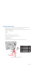
The external control connector on the rear panel lets you remotely access and control the CCC1390H Series camera. The external control
connector assembly is a seven-pin micro (1.25 mm) connector with wires (26 AWG) and connector cover.
You can access and configure the menu settings from any Pelco keyboard, receiver, or other device that supports the Pelco D or Pelco P protocol.
The camera supports the following settings:
• Baud rate: 2400, 4800, 9600, 19200
• Start bit: 1
• Data bits: 8
• Stop bit: 1
• Parity: None
You can also control day/night filter operation from an external switch.
When connecting external control, the wiring should meet the following requirements:
• 24 AWG (0.25 mm
2
) or 22 AWG (0.35 mm
2
)
• Shielded twisted pair
• Up to 4,000 ft (1,219 m) maximum
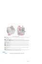
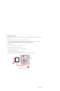
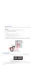
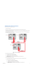
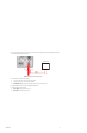
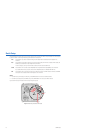
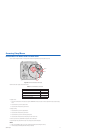
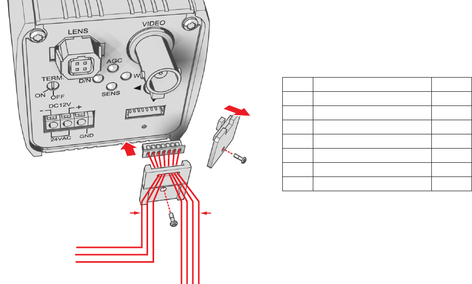
Figure 6 identifies the pin connections for the enclosed external control connector assembly. It also identifies pins 1 and 7.
Figure 6. Installing the External Control Connector
TO CONTROL
DEVICE
GND
RX+
RX-
REMOVE
CONNECTOR
COVER
INSTALL
CONNECTOR
COVER
PIN 7
PIN 1
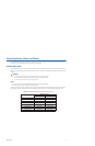
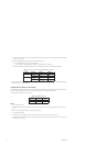
Pin Lead Color
1 Pelco Data RX+ Red
2 Pelco Data RX– White
3 Ground Black
4 Pelco Data TX+ Red
5 Pelco Data TX– White
6 Ground Black
7 Day/Night Control Signal Input Brown