


C1458M-J (9/08) 13
Appendix
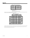
*Cable requirements:
75-ohm impedance
All-copper center conductor
All-copper braided shield with 95% braid coverage
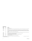
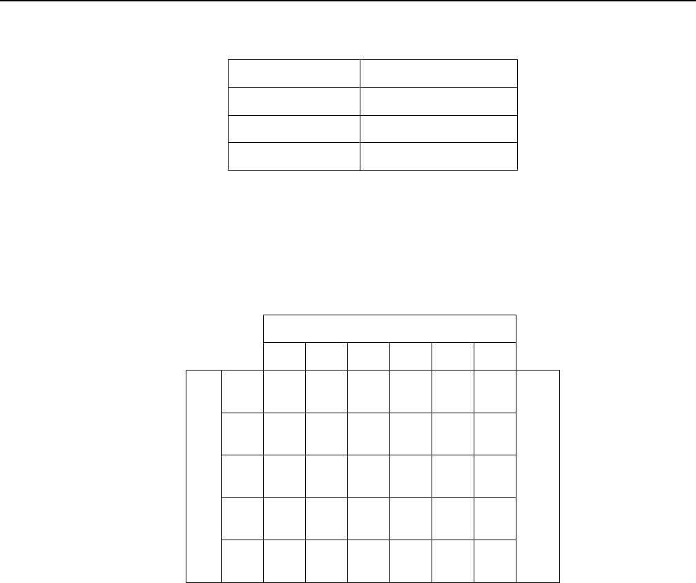
Table B shows are the recommended maximum distances for 24 VAC applications and are calculated with a 10 percent voltage drop. (Ten percent
is generally the maximum allowable voltage drop for AC-powered devices.)
For example, an enclosure that requires 30 VA and is installed 94 ft (28 m) from the transformer would require a minimum wire gauge of 20 AWG.
Models with heaters require 24 VAC for the heater; the heater uses 58 VA. If the camera uses 24 VAC, add the camera power to that of the
heater and refer to Table B to determine the size of wire to use.
Table A. Video Coaxial Cable Wiring Distances
Cable Type* Maximum Distance
RG59/U 750 ft (229 m)
RG6/U 1,000 ft (305 m)
RG11/U 1,500 ft (457 m)
Table B. 24 VAC Wiring Distances
Wire Gauge
20 18 16 14 12 10
Total VA consumed
10
283
(86)
451
(137)
716
(218)
1142
(348)
1811
(551)
2880
(877)
Maximum distance from
transformer to load
20
141
(42)
225
(68)
358
(109)
571
(174)
905
(275)
1440
(438)
30
94
(28)
150
(150)
238
(72)
380
(115)
603
(183)
960
(292)
40
70
(21)
112
(34)
179
(54)
285
(86)
452
(137)
720
(219)
50
56
(17)
90
(27)
143
(43)
228
(69)
362
(110)
576
(175)
NOTE: Distances are calculated in feet; values in parentheses are meters.