10 C3453M-C (5/09)
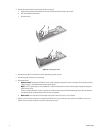
17. Adjust the camera focal length and focus, if necessary.
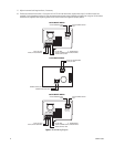
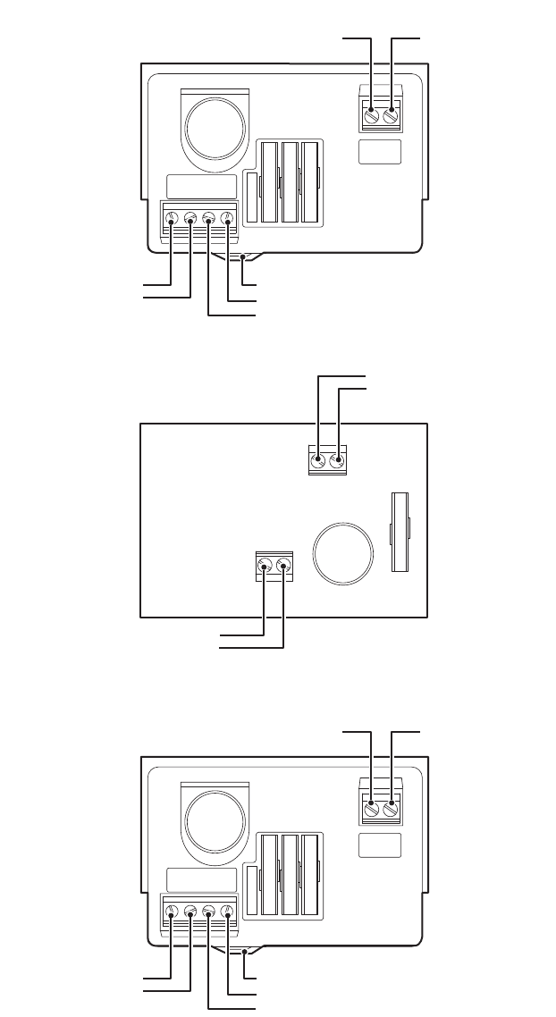
Figure 5. EH1512 Wiring Diagram
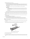
18. Position the enclosure lid and close it. If using the 10-24 x 0.75-inch hex head screws, tighten them using a 5-mm Allen wrench
(not
supplied). If using the optional security kit, insert the three tamper-resistant screws (supplied) and tighten them using the 1/8-inch hollow
screwdriver bit (supplied). When tightening either kind of screw, ensure that the gasket is properly seated.
AC IN
HI NT HI NT
AC OUT
AC IN
HI NT HI NT
AC OUT
HI LOW
24 VAC
HI LOW
24 VAC
LOW HI
AC AC
24 VAC CAMERA OUTPUT
HIGH
INPUT, AC HIGH
INPUT, AC LOW (NEUTRAL)
120 VAC CAMERA OUTPUT, LOW (NEUTRAL)
120 VAC OUTPUT, HIGH
24 VAC CAMERA OUTPUT
LOW
ZIP TIE HERE
120 VAC MODEL WIRING
24 VAC MODEL WIRING
230 VAC MODEL WIRING
24 VAC CAMERA OUTPUT
HIGH
INPUT, AC HIGH
INPUT, AC LOW (NEUTRAL)
230 VAC CAMERA OUTPUT, LOW (NEUTRAL)
230 VAC OUTPUT, HIGH
24 VAC CAMERA OUTPUT
LOW
CAMERA OUTPUT, AC LOW (NEUTRAL)
CAMERA OUTPUT, AC HIGH
INPUT, AC HIGH
INPUT, AC LOW (NEUTRAL)
0 - GROUND BOSS
0 - GROUND BOSS
ZIP TIE HERE
CAMERA
CAMERA


