C3453M-C (5/09) 9
8. (EM1512 mount only) Attach the mount to the wall:
a. Use the mount as a template to mark and drill holes in the mounting surface.
b. Pull the video and power cables from the wall through the mount. If wir
ing with conduit, use a step drill to drill a 0.875 inches (2.22 cm)
hole in one of the three knockout locations for 1/2-inch conduit. (Knockouts are indicated on the side and bottom of the mount arm.)
Refer to Table B on page 11 to determine the size of the power wire needed. Refer to Table D on page 12 to determine the type of video
coaxial cable needed.
c. Fasten the mount to the wall using a minimum of two flat washers (not supplied) and two 1/4-20 bolts (not supplied).
d. Pull the cables through the glands in the enclosure. If the glands are mounted outside the enclosure, tighten the glands around the
cables. (If the glands are mounted inside the enclosure, do not tighten the glands around the cables until after you perform step 9.)
9. (E
M1512 mount only) Attach the enclosure using the threaded mounting holes in the bottom of the enclosure. Use the M6 bolts and 6 mm
split washer (supplied in the parts bag). Tighten the bolts to attach the enclosure body to the mount surface. Tighten the glands around the
cables.
10. (EM1512 mount
only) Adjust the enclosure position by loosening the M6 bolt at the bottom of the mount. Position the mount as desired, and
then tighten the M6 bolt.
11. (For
mounts other than EM1512) Perform the following steps:
a. Install the mount according to the specific installation instructions supplied with the mount.
b. Pull the video and power cables through the glands or conduit on the bottom of the enclosure. Refer to Table B on page 11 to
determine the size of power wire needed. Refer to Table D on page 12 to determine the type of video coaxial cable needed.
NOTE: Be sure to route all coaxial cable and wiring along the sides of the enclosure to avoid heating problems. Maintain separation be
tween
120/230 VAC, 24 VAC, and video wiring.
12. Adjust the glands for a tight fit around the cables. If you are wiring the enclosure with conduit, install the fittings to con
nect the conduit to
the enclosure.
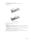
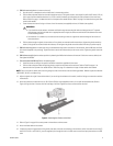
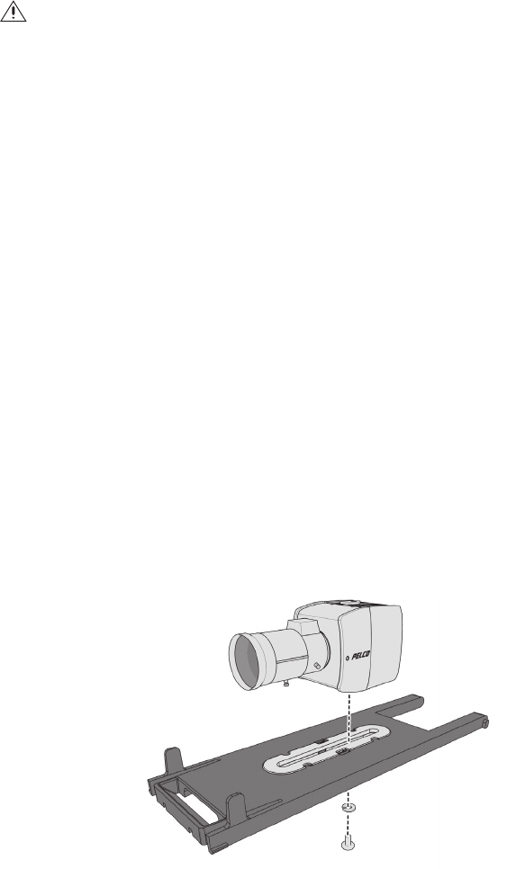
Figure 4. Attaching the Camera to the Sle
d
13. Attach the camera to the sled with the 1/4-20 x 3/8-inch Phillips screw (supplied) and the 1/4-inch split lock washerwasher. (Refer to
Figure 4.) Align the front of the lens with the front edge of the sled. Tighten the screw, and then reinsert the sled.
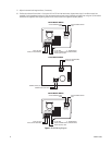
14. Refer to Figure 5 on page 10 to connect power to the enclosure and the camera.
15. Attach the video cables to the camera.
16. If required, connect the ground wire to the ground screw boss an
d screw on the bottom of the enclosure, which is located in front of the PC
board. For EH1512-1 and EH1512-3, pass the supplied zip tie through the hole in the PCB cover to secure the input power wires to the PCB
cover.
WARNINGS:
• If you install the mount outdoors, rainwater could leak through the mounting bolt holes and damage the wall. To prevent
water damage, seal the bolt holes with an appropriate sealant. Apply the sealant around the bolt holes between the mount
and the mounting surface.
• Use fasteners of a suitable size, and make sure the mounting surface can support the combined weight of the mount and
camera/enclosure.


