12 Pelco Manual C1432M-C (11/99)
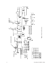
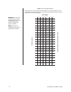
Wire Gauge
Maximum distance from transformer to load
Table A. 24 VAC Wiring Distances
The following are the recommended maximum distances for 24 VAC applications and are
calculated with a 10-percent voltage drop. (Ten percent is generally the maximum allowable
voltage drop for AC-powered devices.)
20 18 16 14 12 10
10 283 451 716 1142 1811 2880
(86) (137) (218) (348) (551) (877)
20 141 225 358 571 905 1440
(42) (68) (109) (174) (275) (438)
30 94 150 238 380 603 960
(28) (45) (72) (115) (183) (292)
40 70 112 179 285 452 720
(21) (34) (54) (86) (137) (219)
50 56 90 143 228 362 576
(17) (27) (43) (69) (110) (175)
60 47 75 119 190 301 480
(14) (22) (36) (57) (91) (146)
70 40 64 102 163 258 411
(12) (19) (31) (49) (78) (125)
80 35 56 89 142 226 360
(10) (17) (27) (43) (68) (109)
90 31 50 79 126 201 320
(9) (15) (24) (38) (61) (97)
100 28 45 71 114 181 288
(8) (13) (21) (34) (55) (87)
110 25 41 65 103 164 261
(7) (12) (19) (31) (49) (79)
120 23 37 59 95 150 240
(7) (11) (17) (28) (45) (73)
130 21 34 55 87 139 221
(6) (10) (16) (26) (42) (67)
140 20 32 51 81 129 205
(6) (9) (15) (24) (39) (62)
150 18 30 47 76 120 192
(5) (9) (14) (23) (36) (58)
160 17 28 44 71 113 180
(5) (8) (13) (21) (34) (54)
170 16 26 42 67 106 169
(4) (7) (12) (20) (32) (51)
180 15 25 39 63 100 160
(4) (7) (11) (19) (30) (48)
190 14 23 37 60 95 151
(4) (7) (11) (18) (28) (46)
200 14 22 35 57 90 144
(4) (6) (10) (17) (27) (43)
Total vA consumed
EXAMPLE:
An enclosure
that requires 80 vA and is
installed 35 feet (10 m) from
the transformer would
require a minimum wire
gauge of 20 AWG.
NOTE:
Distances are
calculated in feet; values in
parentheses are meters.


