


8 Pelco Manual C1432M-C (11/99)
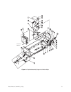
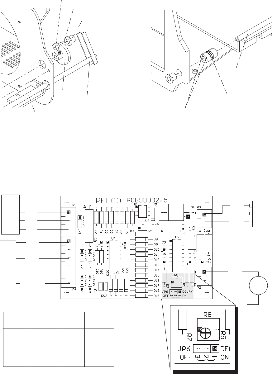
BLU
WHT
BLK
BLK
BLK/WHT
BLU
BLU/WHT
BRN
BRN/WHT
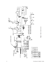
Transformer
Power input to
PCB9000276
BLK
RED
YEL
GRN
C
NO
NC
_
+
M
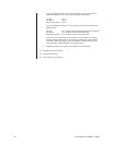
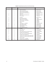
Input Input Input
24 VAC 120 VAC 230 VAC
JP1 1 - 2 2 - 3 2 - 3
JP2 1 - 2 2 - 3 1 - 2
JP3 1 - 2 2 - 3 1 - 2
JP4 1 - 2 2 - 3 2 - 3
JP5 1 - 2 2 - 3 2 - 3
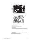
Figure 7. Wiper Circuit Board Component Locations
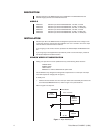
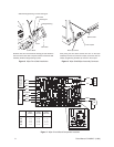
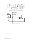
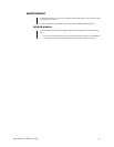
Slide the flange bearing over the bearing pin.
Slide the drive arm forward until the bearing pin sets inside the
cam track of the drive shaft. Only the tautness of the drive shaft
assembly holds the flange bearing in place.
Cam Track
Drive Shaft
Flange Bearing
Bearing Pin
Switch Pin
Cam
Figure 5. Wiper Drive Shaft Installation
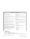
After joining the drive shaft and the drive arm on the wiper
assembly with the use of the flex coupler, secure the drive as-
sembly by tightening the Allen cap screws in the coupler.
Drive shaft.
Flex coupler.
Allen cap screws
Figure 6. Wiper Shaft/Wiper Assembly Connector