Pelco Manual C535M-B (8/98) 7
3.0 INSTALLATION
3.1 THE VIS (COAXITRON
®
) CONTROL SYSTEM
The operating distance for the Vertical Interval Signaling (VIS) system is probably
the most crucial installation parameter. For a VIS control system, the maximum loss
allowed across the coax is 4 dB at 1 MHz. The actual distance for a system without
equalizing amplifiers can be calculated by the following formula.
Distance =4 dB / Loss of the Coax Cable and any Splices
Terminations for the video must be supplied at the controller end of the coax. The
correct termination is 75 ohms. If multiple components such as a VCR or monitors
are on the coax line, the piece of equipment at the extreme end should supply the
only termination.
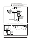
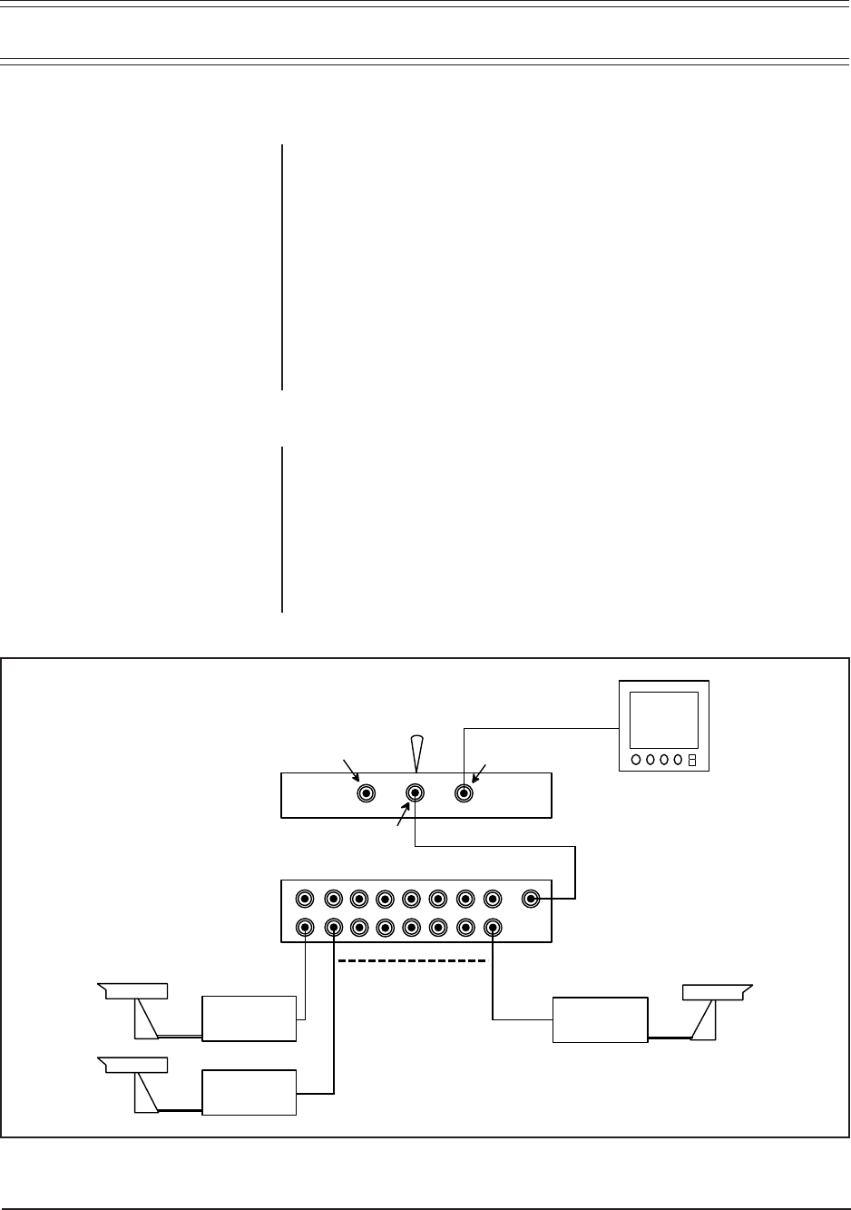
Multiple receivers may be controlled from a single transmitter if a manual or bridg-
ing switcher is used for selection of the desired receiver. Refer to Figure 1.
3.2 THE 4-WIRE RS-485 CONTROL SYSTEM
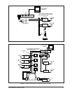
This system is used in applications where multiple receivers will listen to a single
control channel, but duplex operation is desired. The RS-485 system presents sev-
eral unique installation requirements. These requirements are shown in Figure 2
and discussed next.
Excessive connection lengths are not acceptable because they produce reflections
that cause message errors. This means a “star” or “T” topology is not acceptable.
The extreme ends of the cable must have 120-ohm termination resistors to mini-
mize reflections.
NOTE:
“Loss of the Coax Cable
and any Splices” is obtained from
the cable manufacturer’s data
sheets. The splice loss can vary, but
a good splice can be assumed to
add about 0.5 dB loss to the cable.
Figure 1. Multiple Camera Coaxitron
®
System
CX9500
CX9500
CX9500
MON 1
MONITOR OUTPUT
LOOPING OUTPUT
VIDEO INPUT
MPT9500
MANUAL
SWITCHER


