2 Pelco Manual C1973M-B (8/03)
LIST OF TABLES
Table Page
A Baud Rate Switch Settings ................................................................................4
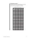
B MRD DIP Switch Settings ..................................................................................5
C Two-Wire Control Connections .........................................................................10
CONTENTS
Section Page
IMPORTANT SAFEGUARDS AND WARNINGS................................................................3
DESCRIPTION...................................................................................................................4
INSTALLATION ..................................................................................................................4
DIP SWITCH SETTINGS ...........................................................................................4
BAUD RATE SELECTION .................................................................................4
MRD ADDRESS SETTINGS..............................................................................5
MRD1400HZ16 INSTALLATION METHODS .............................................................6
WALL MOUNTING .............................................................................................6
DF5/DF8 SERIES DOME INSTALLATION ........................................................6
EH3512 SERIES ENCLOSURE INSTALLATION ..............................................8
EH2512 SERIES ENCLOSURE INSTALLATION ..............................................9
CONTROL, POWER, AND CAMERA CONNECTIONS ............................................10
OPERATION .....................................................................................................................11
TROUBLESHOOTING ......................................................................................................12
WARRANTY AND RETURN INFORMATION....................................................................12
LIST OF ILLUSTRATONS
Figure Page
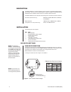
1 SW-1 Default Switch Settings ............................................................................4
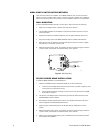
2 Wall Mounting ....................................................................................................6
3 DF5/DF8 Installation ..........................................................................................7
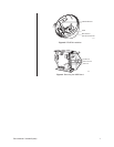
4 Removing the MRD Board .................................................................................7
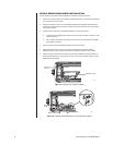
5 Installing the EH3512 Adapter ...........................................................................8
6 Installing the MRD Board onto the EH3512 Adapter..........................................8
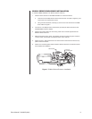
7 EH2512 Series Enclosure Installation................................................................9
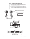
8 Control, Power, and Camera Connections........................................................10
9 Multiple Units with Parallel Connections ...........................................................10
10 Data Cable Wiring .............................................................................................10


