


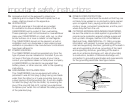
15. Apparatus shall not be exposed to dripping or
splashing and no objects filled with liquids, such as
vases, shall be placed on the apparatus.
16.
VENTILATION:
Slots and openings in the cabinet are provided
for ventilation to ensure reliable operation of the
CAMCORDER and to protect it from overheating.
These openings must not be blocked or covered.Never
place your CAMCORDER on a bed, sofa, rug, or other
similar surface: on or near a radiator or heat register.
This CAMCORDER should not be placed in a built-in
installation such as a bookcase or rack unless proper
ventilation is provided or the manufacturer's instructions
have been adhered to.
17.
POWER SOURCES:
The CAMCORDER should be operated only from the
type of power source indicated on the label. If you are
not sure of the type of power supply at your home,
consult your appliance dealer or local power company.
A CAMCORDER is intended to be operated from
battery power, or other sources, refer to the operating
instructions.
18.
GROUNDING OR POLARIZATION:
This CAMCORDER may be equipped with either a
polarized 2-wire AC line plug (a plug having one blade
wider than the other) or a 3-wire grounding type plug,
a plug having a third (grounding) pin. If you are unable
to insert the plug fully into the outlet, try reversing the
plug. If the plug still fails to fit, contact your electrician
to replace your outlet. Do not defeat the safety purpose
of the polarized plug.
19.
POWER-CORD PROTECTION:
Power-supply cords should be routed so that they are
not likely to be walked on or pinched by items placed
upon or against them, paying particular attention to
cords or plugs, convenient receptacles, and the point
where they exit from the unit.
20.
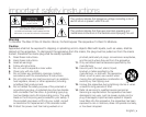
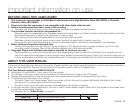
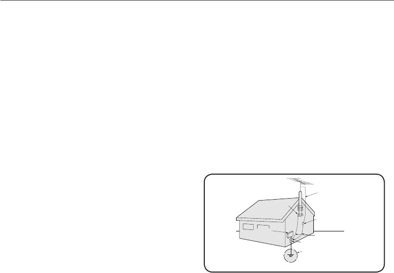
OUTDOOR ANTENNA GROUNDING:CAMCORDER,
be sure the antenna or cable system is grounded to
provide some protection against voltage surges and
built-up static charges, Section 810 of the National
Electrical Code, ANSI/NFPA No. 70-1984, provides
information with respect to proper grounding of the
mast and supporting structure, grounding of the lead-in
wire and supporting structure, grounding of the mast
and supporting structure, grounding of the lead-in
wire to an antenna discharge unit, size of grounding
to conductors, location of antenna-discharge unit,
connection to grounding electrodes and requirements
for the grounding electrode. See figure below.
GROUNDING CONDUCTORS
(NEC SECTION 810-21)
GROUND CLAMPS
POWER SERVICE GROUNDING
ELECTRODE SYSTEM
(NEC ART 250, PART H)
NEC NATIONAL ELECTRICAL CODE
ELECTRIC
SERVICE
EQUIPMENT
GROUND
CLAMP
ANTENNA
LEAD IN
WIRE
ANTENNA
DISCHARGE UNIT
(NEC SECTION 810-20)
important safety instructions
vi_English