


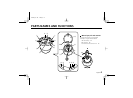
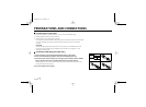
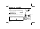

PARTS NAMES AND FUNCTIONS
1 Camera unit fixing screws (4)
These screws are used to attach the camera unit to the base.
Tighten the four screws evenly when attaching the camera unit.
2 Screw openings for base installation
These openings are to attach the base to the ceiling or a wall
using the four supplied tapping screws.
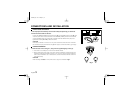
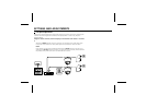
3 CAMERA (VIDEO) OUT terminal screw
Video signal output terminal. Insert the center wire of the coaxial
cable into the CAMERA OUT terminal, then tighten the screw to
secure it.
4 GND (ground) terminal screw
Video signal ground terminal. Insert the shielding mesh of the
coaxial cable under the GND terminal plate, then tighten the
screw to secure it.
5 Cabling tab
When the cables cannot be run behind the ceiling, etc., remove
this tab to allow the coaxial cable to go through.
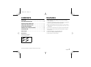
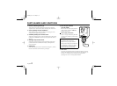
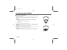
6 24 V AC input terminal
(24 V AC, GND)
With this camera use only the 24 V AC
power adaptor model No. VPT-115
available from Sanyo.
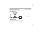
Power supply connections
Use a 3 wire grounded cable (22 AWG
or more), and connect as shown by the
illustration.
CAUTION:
•To prevent camera and/or AC
adaptor failure, pay close attention
polarity when making the connections.
•To prevent fire hazard any UL listed
wire rated VW-1, should be used for
the 24 V AC cable input terminal.
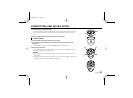
7 Lens cover
This cover will protect the lens from dust and damage. Turn the
cover in the direction of the arrow, shown on the illustration, to
remove it. To install the cover, align the tabs (A) with the
openings, then turn it in the opposite direction.
GND
AC
AC
L73D4/US GB 1998, 3, 12
English 5