2
Name and Function of Each Component
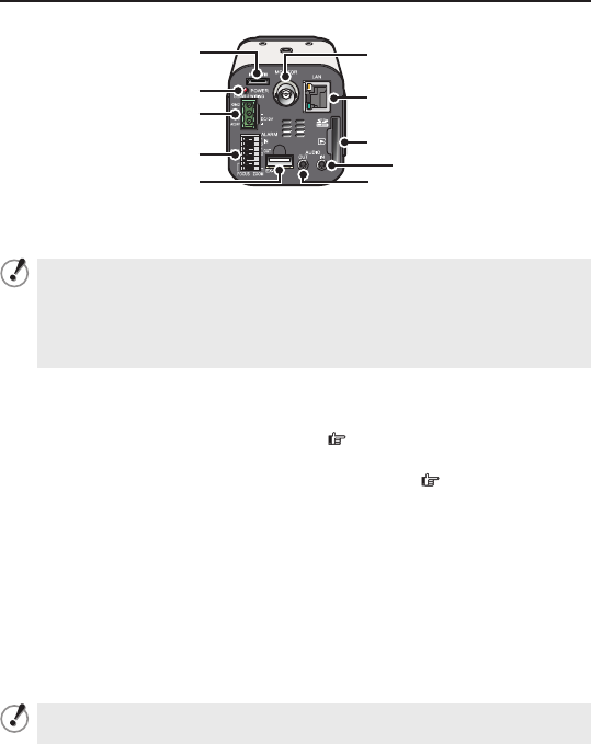
Rear Face
Power Indicator (POWER)
This indicator lights up when the camera is powered on.
When the camera is on, this indicator blinks to indicate the following
camera statuses:
Firmware update in progress
Deactivation of media recording is in progress.
Error occurring on SD memory card or external hard disk drive (faster
blink)
•
•
•
24 VAC/ 12 VDC Power Connector Terminal
Connect a 24 VAC or 12 VDC power supply to this terminal using the supplied
Power supply connector.
For details, refer to the “Basic Connections” (
Page 6) section.
Control Terminals (7 push-lock pins)
For details, refer to the “ Control Terminal Connections” (
Page 7) section.
External hard disk terminal (EX-HDD)
To record live video on a hard disk, put the hard disk in a dedicated hard disk case
(VA-HDC4000), sold separately) and then connect the case to the camera.
For details, refer to “Installing and formatting recording media” section on the
electronic manual.
Audio Output Jack (AUDIO OUT, 3.5-mm mini jack)
Connect this jack via an audio cable to the audio input jack of an amplified speaker
system or the monitor.
Audio Input Jack (AUDIO IN, 3.5-mm mini jack)
Use this jack to connect an external microphone to listen to the sound while
monitoring the live video, or simultaneously record the video and sound.
This jack supports 3.5-mm diameter monaural microphone plugs, or
monaural line-level input plugs (the left channel only for stereo plugs).
■


