


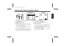

PARTS NAMES AND FUNCTIONS
1
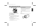
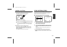
Video output connector (VIDEO OUT: BNC type)
Connect this connector to a device such as a time lapse VCR or
monitor with a
VIDEO IN
connector.
2
Power indicator (POWER)
Comes on when the power to the camera is on.
Note:
After connecting the power supply the POWER indicator
will blink for 5 seconds. During this time no adjustments
using the menus or any other operation are possible.
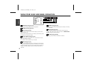
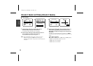
3
Cursor button (See p8)
j: Press this button to move the cursor up.
c: Press this button to move the cursor to the right, or to
turn the settings ON/OFF etc.
d: Press this button to move the cursor to the left, or to turn
the settings ON/OFF etc.
l: Press this button to move the cursor down.
4
SET button (SET) (See p8)
Connect the camera to the monitor, then press the
SET
button for about 3 seconds to display the on-screen menu.
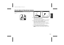
5
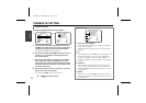
RS-485 control push-lock terminals (RS485, A, B, G)
Use a cable thicker than AWG22.
A:
Twisted-pair cable terminal
G:
Ground terminal
B:
Twisted-pair cable terminal
6
24 V AC or 12 V DC input terminals (AC 24 V, DC 12 V,
GND)
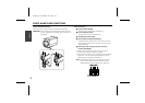
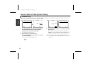
Lens cap
The cap is installed to protect the lens section. Remove the cap
when using the camera.
SET
RS485
GND
AC24V
DC12V CLASS 2 WIRING
ABG
POWER
VIDEO OUT
FOCUS ALARM
IN
OUT
ZOOM COM
2
5
6
4
3
1
Control
terminals
L5AD2/US (VCC-ZM400) GB 2003, 2, 4
English
4