


– 12 –
ASIC,
memory
CCD
8 bit
CPU
MODE
LCD
LCD
MONITOR
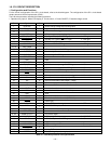
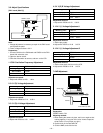
Supply voltage
Power OFF
Play back
Shutter switch ON
Resolution, Flash,
Self timer switch ON
LCD finder
3.3 V
5 V (A)
+12 V etc.
3.2 V
(ALWAYS)
3.2 V
(ALWAYS)
5V (L)
+12V etc.
OFF
OFF
32KHz OFF OFF
OFF
OFF
4 MHz ON OFF
ON
ON OFF
4 MHz ON OFF
OFF
OFF
4 MHz ON OFF
ON
ON
4 MHz ON ON
ON
OFF
4 MHz ON ON
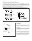
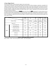
Table 4-3. Camera Mode (Battery Operation)
Note) P. SAVE = 4 MHz = Main clock operation, 32 kHz = Sub clock operation
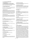
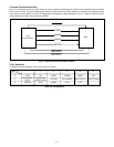
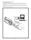
4. Power Supply Control
The 8-bit microprocessor controls the power supply for the overall system.
The following is a description of how the power supply is turned on and off. When the battery is attached, a regulated 3.2 V
voltage is normally input to the 8-bit microprocessor (IC301) by IC302, so that clock counting and key scanning is carried out
even when the power switch is turned off, so that the camera can start up again. When the battery is removed, the 8-bit micro-
processor operates in sleep mode using the backup capacitor. At this time, the 8-bit microprocessor only carries out clock
counting, and waits in standby for the battery to be attached again. When a switch is operated, the 8-bit microprocessor supplies
power to the system as required.
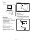
The 8-bit microprocessor first sets both the P (A) ON signal at pin (70) and the P ON signal at pin (71) to high, and then turns on
the DC/DC converter. After this, low signals are output from pins (96), (97) and (98) so that the ASIC is set to the active condition.
If the LCD monitor is on, the LCD ON signal at pin (95) set to high, and the DC/DC converter for the LCD monitor is turned on.
Once it is completed, the ASIC returns to the reset condition, all DC/DC converters are turned off and the power supply to the
whole system is halted.
Power switch ON-
Auto power down
CAM