


– 7 –
1-3. CA3 CIRCUIT DESCRIPTION
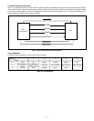
1. Outline
This is the main CA3 power block, and is comprised of the
following blocks.
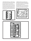
Switching controller (IC521)
Analog system 5.0 V power output (L5201, Q5203, D5201,
C5206)
Backlight power output (L5101, Q5102, D5101, C5106)
2. Switching Controller (IC521)
This is the basic circuit which is necessary for controlling the
power supply for a PWM-type switching regulator, and is pro-
vided with one built-in channel. Feedback from 5 V (A) power
supply output is received, and the PWM duty is varied so that
each one is maintained at the correct voltage setting level.
2-1. Short-circuit protection circuit
If output is short-circuited for the length of time determined
by the condenser which is connected to Pin (2) of IC521, all
output is turned off. The control signal (P ON, P(A) ON and
LCD ON) are recontrolled to restore output.
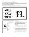
3. Switching Controller (IC511)
This is the basic circuit which is necessary for controlling the
power supply for a PWM-type switching regulator, and is pro-
vided with one built-in channel. Feedback from 10 mA (L)
power supply output is received, and the PWM duty is varied
so that each one is maintained at the correct current setting
level.
3-1. Protection circuit
If output is short-circuited for the length of time determined
by the condenser which is connected to Pin (2) of IC511 the
output is shorted out or the backlighting is open (there is no
connection between CN512 and the backlight unit), output
will turn off. all output is turned off. The control signal (P ON,
P(A) ON and LCD ON) are recontrolled to restore output.
4. Analog system 5.0 V Power Output
5 V (A) is output. Feedback is provided to the swiching con-
troller (Pin (1) of IC521) so that PWM control can be carried
out.
5. Backlight Power Output
10 mA (L) is output. The backlighting turns on when current
flows in the direction from pin (1) to pin (2) of CN512. At this
time, a feedback signal is sent from pin (2) of CN512 to pin
(1) of IC511 so that PWM control is carried out to keep the
current at a constant level (10 mA).