20 Cheetah 10K.6 FC Product Manual, Rev. B
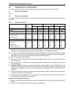
3. Where power is provided to multiple drives from a common supply, careful consideration for individual drive
power requirements should be noted. Where multiple units are powered on simultaneously, the peak start-
ing current must be available to each device.
4. Parameters, other than spindle start, are measured after a 10-minute warm up.
5. No terminator power.
6.2.1 Conducted noise immunity
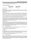
Noise is specified as a periodic and random distribution of frequencies covering a band from DC to 10 MHz.
Maximum allowed noise values given below are peak-to-peak measurements and apply at the drive power
connector.
6.2.2 Power sequencing
The drive does not require power sequencing. The drive protects against inadvertent writing during power-up
and down.
6.2.3 Current profiles
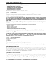
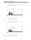
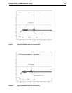
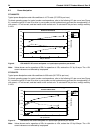
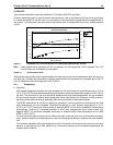
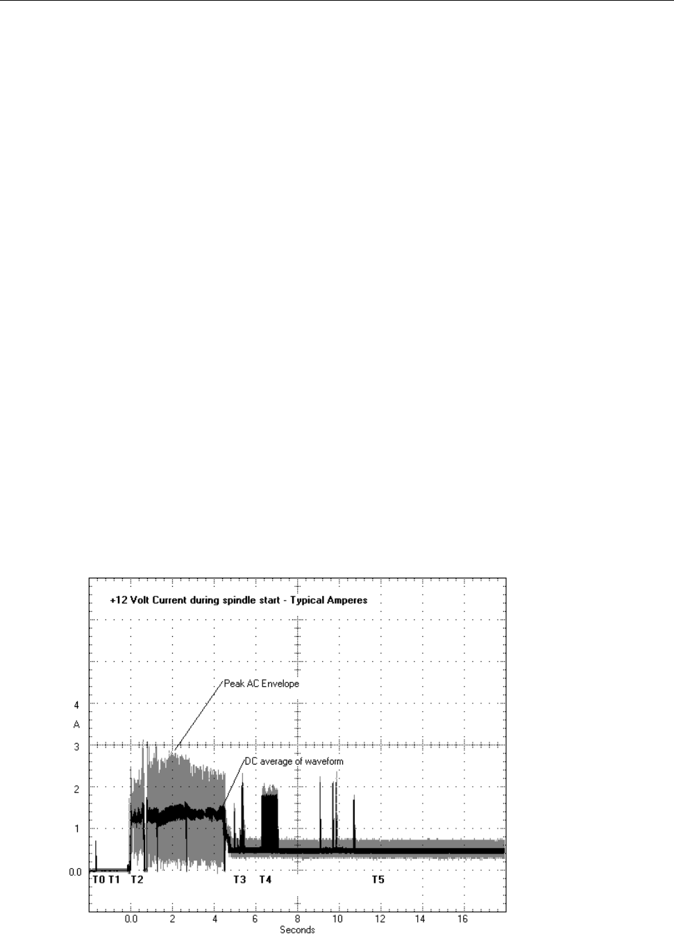
Figures 3, 4 and 5 identify the drive +12V current profiles for each model ST3146807FC, ST3733307FC and
ST336607FC, respectively. The current during the various times is as shown:
T0 Power is applied to the drive.
T1 Controller self-tests are performed.
T2 Spindle begins to accelerate under current limiting after performing internal diagnostics.
T3 Spindle is up to speed and the Head-Arm restraint is unlocked.
Note: All times and currents are typical. See Table 1 for maximum current requirements.
Figure 3. Typical ST3146807FC drive +12V current profile
+5V +12V
0 to 100 kHz 150mV 150mV
100 kHz to 10 MHz 100mV 100mV


