


Cheetah 10K.6 FC Product Manual, Rev. B 57
The Active LED Out signal is designed to pull down the cathode of an LED. The anode is attached to the proper
+5 volt supply through an appropriate current limiting resistor. The LED and the current limiting resistor are
external to the drive.
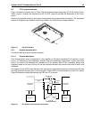
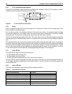
9.5.9 Enable port bypass signals
The – Enable Bypass Port A (– EN BYP Port A) and – Enable Bypass Port B (– EN BYP Port B) signals control
the port bypass circuits (PBC) located external to the disc drive. The PBC allows a loop to remain functional in
the event of a drive failure or removal. When these signals are active, low, the PBC bypasses the drive on the
associated port. When an Enable Bypass signal is active, the corresponding Port Bypass LED signal in con-
nector J1 is driven low by the disc drive. A pull down resistor, 1K, located with the PBC should be used to
insure the bypass is enabled if the disc drive is not installed.
The Enable Bypass signal is active under failing conditions within the drive, on detection of the Loop Port
Bypass primitive sequence, or on removal of the drive. In the bypass state the drive continues to receive on the
inbound fibre. Enable Bypass may be deactivated by detection of a Loop Port Enable primitive sequence if the
drive has completed self-test and a hardware failure is not present.
Failure modes detected by the disc drive that will enable bypass include:
• Transmitter/receiver wrap test failure
• Loss of receive clock
• Loss of transmission clock
• Drive interface hardware error
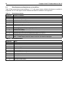
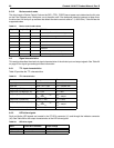
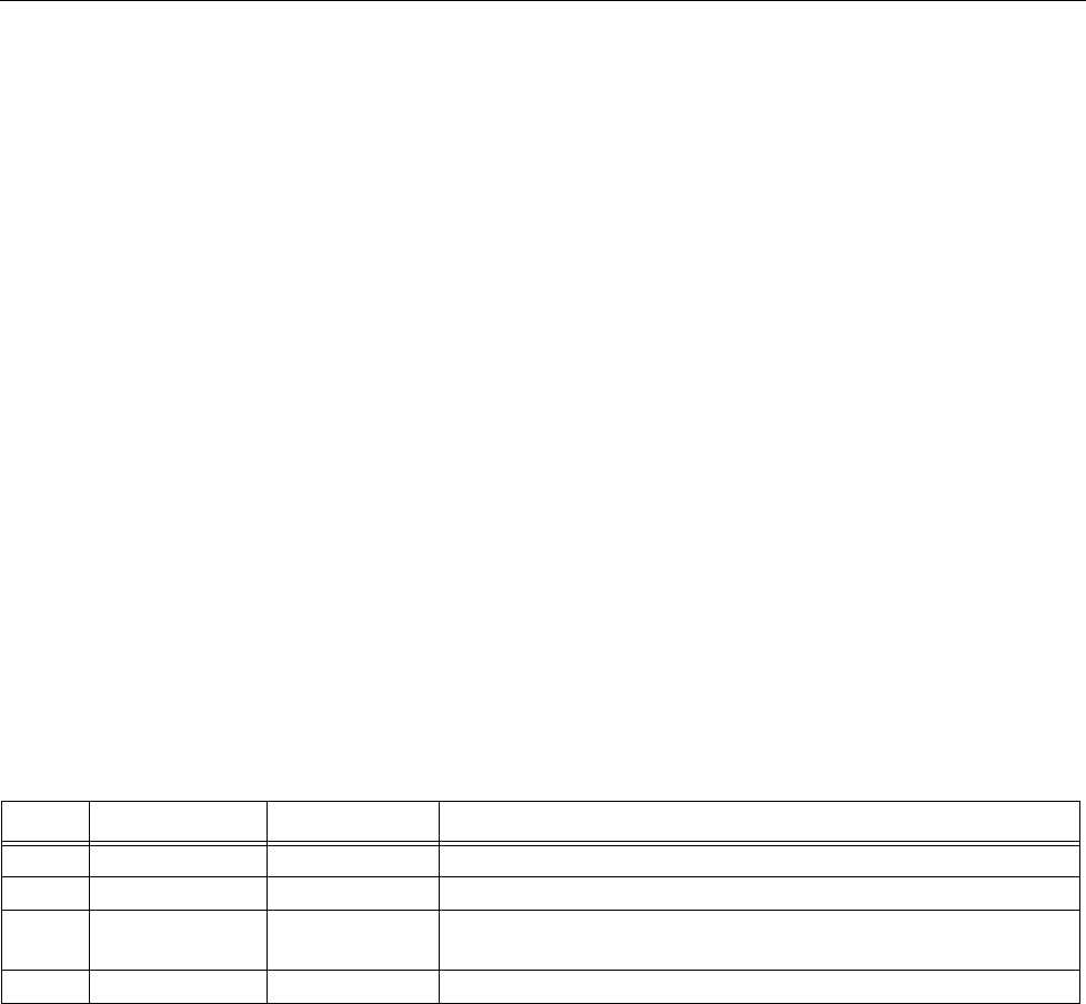
9.5.10 Motor start controls
The drive’s motor is started according to the Start_1 and Start_2 signals described in Table 22. The state of
these signals can be wired into the backplane socket or driven by logic on the backplane.
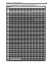
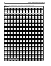
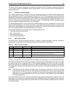
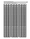
9.5.11 SEL_6 through SEL_0 ID lines
The SEL_6 through SEL_0 ID lines determine drive address, and, optionally, for an Enclosure Services Inter-
face. When the Parallel ESI line is high, the enclosure backpanel must provide address information on the SEL
line. Refer to table 23 for a mapping of SEL to FC-AL physical addresses (AL_PA). You can think of the SEL
lines as the equivalent of a backpanel logic plug. The drives does not provide pull up resistors on these lines.
The backpanel is required to provide high and low inputs to the SEL_ID lines per the specifications in table 25
on page 60.
Note. Table 23 gives AL_PA values for each SEL value. The first entry in the table is SEL_ID 00. The last
entry is SEL_ID 7D. SEL_ID 7E is AL_PA 00 which is not valid for an NL_Port, so is not included in the
table. Also, SEL_ID 7Fh does map to a valid AL_PA; however, this value signals the drive that physical
addresses are not being assigned using the SEL lines and that a “soft” address will be determined by
FC-AL loop initialization.
When the Parallel ESI line is low, the enclosure backpanel logic switches to ESI mode if supported. There are
two modes of ESI, seven bits of enclosure status and a bidirectional mode. ESI support and the mode are
determined by the drive using a discovery process. Refer to the
Fibre Channel Interface Manual
for a descrip-
tion of ESI operation.
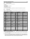
Table 22: Motor start control signals
Case Start_2 Start_1 Motor spin function
1 Low Low Motor spins up at DC power on.
2 High Low Motor spins up only when SCSI Start command is received.
3 Low High Motor spins up after a delay of 12 seconds times the modulo 8 value of
the numeric SEL ID of the drive from DC power on.
4 High High The drive will not spin up.