


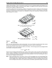

Cheetah 10K.6 FC Product Manual, Rev. B 31
7.0 Defect and error management
The drive, as delivered, complies with this product manual. The read error rates and specified storage capaci-
ties are not dependent upon use of defect management routines by the host (initiator).
Defect and error management in the SCSI protocol involves the drive internal defect/error management and
FC-AL system error considerations (errors in communications between the initiator and the drive). Tools for use
in designing a defect/error management plan are briefly outlined in this section. References to other sections
are provided when necessary.
7.1 Drive internal defects/errors
During the initial drive format operation at the factory, media defects are identified, tagged as being unusable,
and their locations recorded on the drive primary defects list (referred to as the “P’ list and also as the ETF
defect list). At factory format time, these known defects are also reallocated, that is, reassigned to a new place
on the medium and the location listed in the defects reallocation table. The “P” list is not altered after factory
formatting. Locations of defects found and reallocated during error recovery procedures after drive shipment
are listed in the “G” list (defects growth list). The “P” and “G” lists may be referenced by the initiator using the
Read Defect Data command.
Details of the SCSI commands supported by the drive are described in the
Fibre Channel Interface Manual
.
Also, more information on the drive Error Recovery philosophy is presented in the
Fibre Channel Interface
Manual
.
7.2 Drive error recovery procedures
When an error occurs during drive operation, the drive, if programmed to do so, performs error recovery proce-
dures to attempt to recover the data. The error recovery procedures used depend on the options previously set
in the Error Recovery Parameters mode page. Error recovery and defect management may involve using sev-
eral SCSI commands described in the
Fibre Channel Interface Manual
. The drive implements selectable error
recovery time limits required in video applications.
The error recovery scheme supported by the drive provides a way to control the total error recovery time for the
entire command in addition to controlling the recovery level for a single LBA. The total amount of time spent in
error recovery for a command can be limited using the Recovery Time Limit bytes in the Error Recovery mode
page. The total amount of time spent in error recovery for a single LBA can be limited using the Read Retry
Count or Write Retry Count bytes in the Error Recovery mode page.
The drive firmware error recovery algorithms consists of 12 levels for read recoveries and five levels for write.
Each level may consist of multiple steps, where a step is defined as a recovery function involving a single re-
read or re-write attempt. The maximum level used by the drive in LBA recovery is determined by the read and
write retry counts.
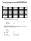
Table 2 equates the read and write retry count with the maximum possible recovery time for read and write
recovery of individual LBAs. The times given do not include time taken to perform reallocations. Reallocations
are performed when the ARRE bit (for reads) or AWRE bit (for writes) is one, the RC bit is zero, and the recov-
ery time limit for the command has not yet been met. Time needed to perform reallocation is not counted
against the recovery time limit.