


Chapter 1 Overview
Chapter 1 Overview 27
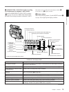
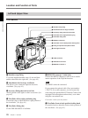
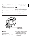
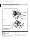
8 Fitting for optional microphone holder
You can fit an optional CAC-12 Microphone Holder
here. (See page 43.)
9 Video light connector
A video light with a maximum power consumption of
30 W such as the Anton Bauer Ultralight 2 or
equivalent can be connected.
0 LENS connector (12-pin)
If you use a lens with cable, connect the lens cable.
qa VIDEO OUT connector (BNC)
This outputs the video signal captured by the
camcorder.
qs REMOTE connector 2 (10-pin)
Connect the optional RM-M7G Remote Control Unit
to this connector. Set the CAMERA SELECT switch
on the bottom of RM-M7G to 1.
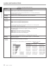
Notes
• EZ mode cannot be used if the RM-M7G is
connected to the camcorder.
•Be sure to turn off the power of the camcorder before
connecting the RM-M7G.
•Be sure to turn off the power of the camcorder before
disconnecting the equipment connected to this
connector. Otherwise, the camcorder will not work
properly.
• To control this unit from a CCU (camera control
unit), connect the RM-M7G to the CCU.
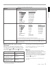
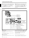
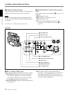
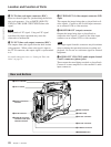
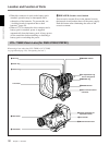
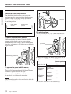
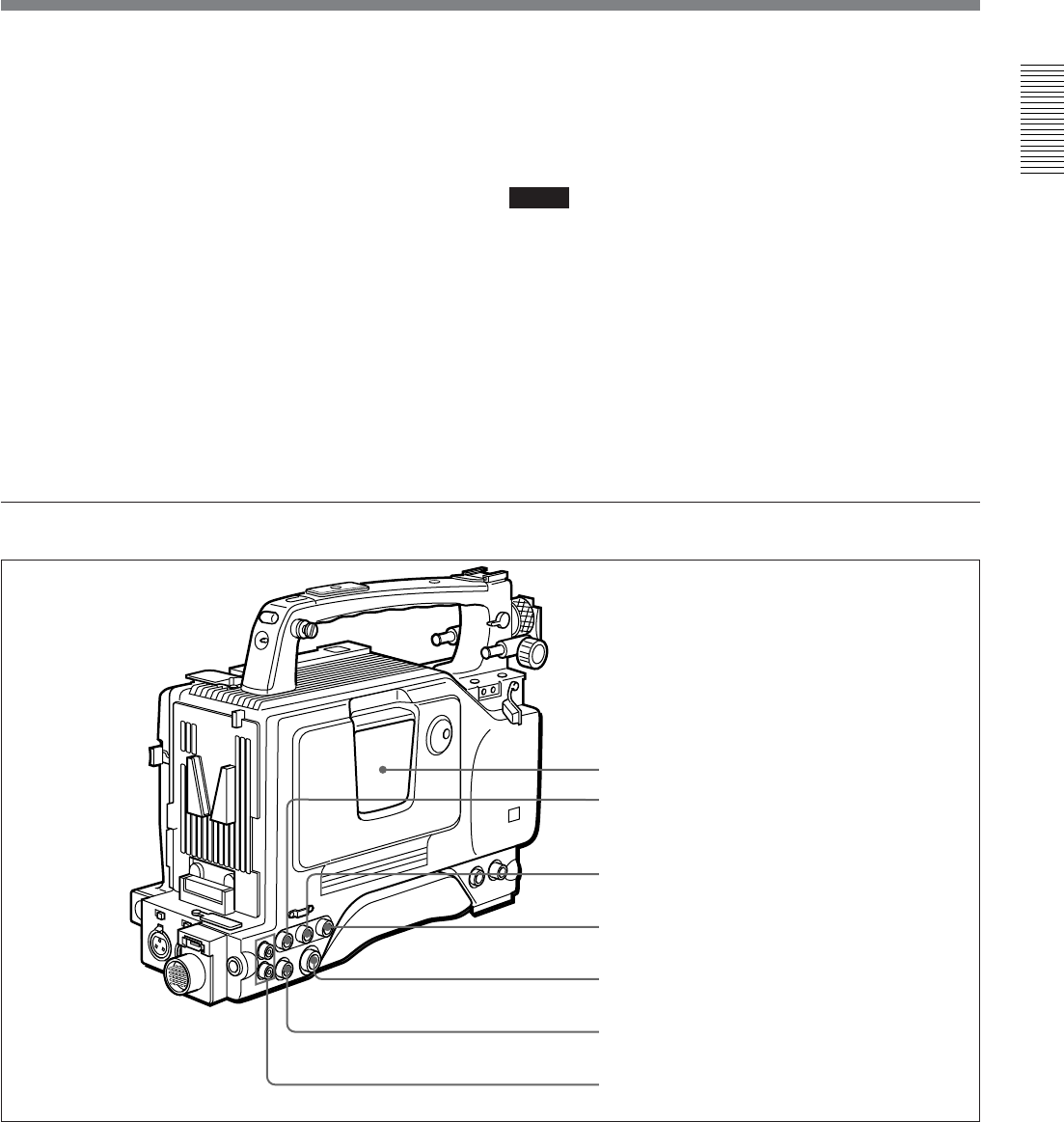
Rear section
1 Cassette holder
Power the camcorder and press the EJECT button to
open the lid. Insert the cassette and close the lid by
pressing the indication “PUSH” .
2 GEN LOCK IN (gen lock video input)/VIDEO
IN (video input) connector (BNC)
1 Cassette holder
2 GEN LOCK IN/VIDEO IN connector
a)
3 TC IN connector
4 TC OUT connector
5 S VIDEO OUT connector
6 MONITOR OUT connector
7 AUDIO OUT CH-1/CH-2 connectors
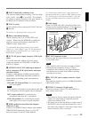
GEN LOCK IN: When synchronizing the camcorder
to an external signal, input a reference video
signal (VBS or BS). (See page 93.)
VIDEO IN: When the optional DSBK-501/501P
Analog Composite Input Board is fitted to the
camcorder, you can input the analog video signals
(VBS) to this connector.
a) When the optional DSBK-501/501P is fitted