


Chapter 1 Overview
36 Chapter 1 Overview
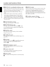
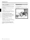
Location and Function of Parts
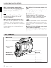
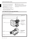
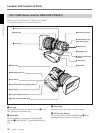
6 REC/TALLY (recording/tally) indicators (red)
• These flashe from the time when you press the VTR
button on the lens or camcorder until recording starts,
then stay on continuously during recording.
• These are also used to indicate a fault. (See page
142.)
• When a CCU (camera control unit) is connected,
these indicators light only when a CALL signal is
received from the CCU. They do not light or flash
during VCR recording or in the case of a VCR fault.
• The lower indicator can be disabled by menu setting.
(See page 102.)
7 GAIN UP indicator (orange)
This lights when the gain is 3 dB or more.
8 SHUTTER indicator (red)
This lights when the SHUTTER switch (5 on page
15) is in the ON position. (If the EVS is selected, the
indicator will not light.)
9 PEAKING control
This adjusts the outline intensity of the viewfinder
image. (See page 132.)
0 CONTRAST control
This adjusts the contrast of the viewfinder image. (See
page 132.)
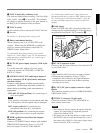
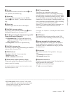
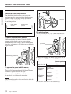
qa Tally lamp
When the TALLY switch qf is in the ON position, this
operates in the same way as the REC/TALLY
indicators 6.
qs BRIGHT (brightness) control
This adjusts the brightness of the viewfinder image.
(See page 132.)
qd Eyepiece release catch
To view the viewfinder screen directly, press this
catch, and hinge up the eyepiece.
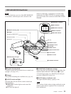
qf TALLY switch
Set this switch to the ON position to use the tally lamp
qa.
qg DISPLAY switch
Set this switch to OFF when you want to remove the
character data from the viewfinder and the monitor
connected to the MONITOR OUT connector.
However, items which are set to OFF in advanced
menu page 5 and page 6 are not displayed even when
this switch is set to ON.
qh Viewfinder connector (20-pin)
Connect this to the VF connector (2 on page 15).