


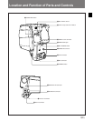
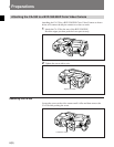

Location and Function of Parts and Controls
4(E)
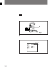
5 EARPHONE jack (minijack)
Connect an earphone. Depending on an internal
setting, you can monitor either the audio from the VTR
or the microphone input. The factory setting is for
monitoring the audio from the VTR.
For more information about the internal setting, contact
Sony service personnel.
6 MIC (microphone) POWER switch
When a microphone of phantom powering type is
connected to the CA-530, set this switch to +48V to
power the microphone.
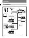
7 REMOTE connector (8-pin)
Connect an RCP-700 series remote control panel or
RM-B150 remote control unit.
To connect an RCP-700 series: Use an optional
CCA-5-10 or CCA-5-3 cable.
To connect an RM-B150: Use the cable supplied
with it.
8 VTR connector (26-pin)
Connect to the CAMERA connector of a VTR or AC
adaptor to input or output video, audio and control
signals as well as a power supply.
When the POWER switch 0 is set to SDI OFF, the
SDI signal is not output from this connector. Analog
signals only are output.
9 MIC (microphone) connector (XLR type, 3-pin)
Connect an external microphone.
The microphones connected to the MIC IN connector
of the BVP-550/550P and the MIC connector of the
CA-530 correspond to the CH1 and CH2 settings of
the AUDIO IND switch 1, respectively.
To power an external microphone of phantom
powering type, set the MIC POWER switch 6 to
+48V.
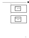
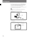
!º POWER switch
Switches the power supply as follows.
11
11
1 SDI OFF: The CA-530 enters power saving mode.
The power supply to its digital system is shut off,
allowing only its analog system to function.
¬¬
¬¬
¬: The power supply is shut off, disabling the CA-
530.
11
11
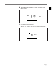
1 SDI ON: The CA-530 is powered and all of its
functions are enabled.
1 AUDIO IND (indicator) switch
Selects either of the following two microphone inputs.
CH1: Microphone input from the MIC IN connector
of the BVP-550/550P
CH2: Microphone input from the MIC connector of
the CA-530
The setting of this switch determines the contents of
the following signals.
• Microphone input whose audio level is indicated on
the viewfinder screen.
• Analog audio signals output to the VTR
• Microphone input monitored from the EARPHONE
jack 5 (This is only when the microphone input is
selected by an internal setting. See the section “5
EARPHONE jack”.)
2 MIC (microphone) LEVEL control
Adjusts the audio level of the microphone input to be
multiplexed on the SDI output signal of the CA-530.
Depending on an internal setting, you can monitor the
microphone audio adjusted with this control through
the EARPHONE jack (see the section “5
EARPHONE jack”). The microphone audio level is
indicated on the viewfinder screen.
For more information about the audio level indication on
the viewfinder screen, refer to the operation manual
provided with the BVP-550/550P.
3 TALLY lamp and TALLY switch
When the TALLY switch is set to ON, the TALLY
lamp functions as follows.
Flashes: The battery connected to the CA-530 is
about to exhaust, or a low-battery-voltage signal
has been received from the VTR.
Lights: The battery connected to the CA-530 has
completely exhausted, or a battery exhaustion
signal has been received from the VTR.
When the TALLY switch is set to OFF, the TALLY
lamp does not function.
4 SERIAL OUT (serial data output) connector
(BNC type)
Outputs a digital signal complying with the SMPTE
259M standard. You can connect equipment (for
example, a video editor) provided with an SDI input
connector to this connector. Signal transmission is
possible up to 200 m using a coaxial transmission
cable (impedance 75 ohms).
When the POWER switch is set to SDI OFF, this
connector does not function.