


13
OUTPUT
S VIDEO
S VIDEO
RGB
R -Y. Y.
B-Y
B/
B-Y
G-Y
R/
R-Y
IN IN IN 1 2
OUT OUT OUT
75Ω 75Ω 75Ω
VBS OUT
MONITOR
OUT
SYNC OUT
GENLOCK
PROMPT
VIDEO
RETURN
VIDEO
REMOTE ~AC IN
MIC OUT
TALLY/
INTERCOM
GYX
CAMERA
INTERCOM TALLY
ON OFF ON OFF ON OFF
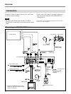
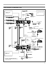
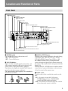
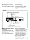
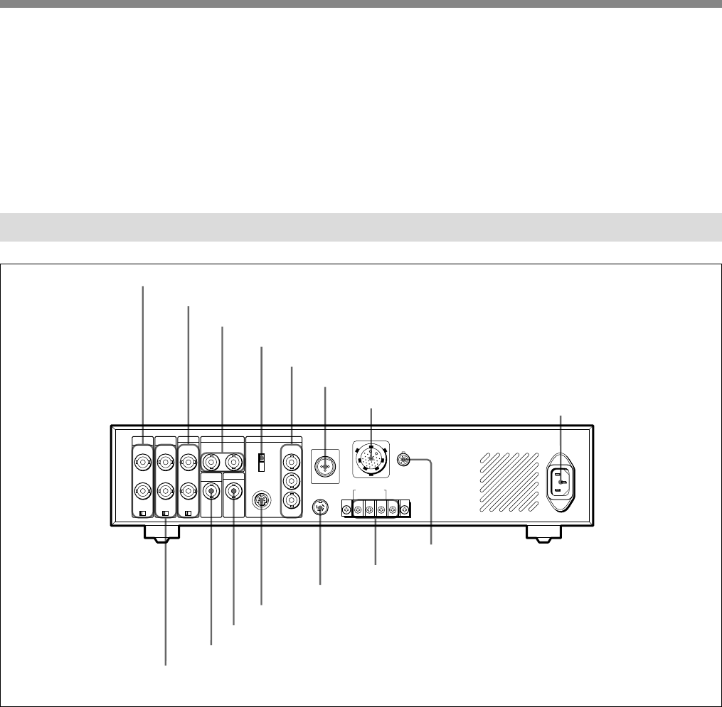
1 PROMPT VIDEO IN/OUT connectors and 75Ω termination switch
2 GENLOCK IN/OUT connectors and 75Ω termination switch
3 VBS OUT 1/2 connectors
4 OUTPUT switch
5 R/R-Y, G/Y, and B/B-Y connectors
6 MIC OUT connector
7 CAMERA connector
8 AC IN connector
9 REMOTE connector
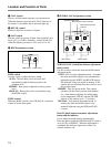
q; INTERCOM/TALLY terminals
qa TALLY/INTERCOM connector
qs S VIDEO connector
qd SYNC OUT connector
qf MONITOR OUT connector
qg RETURN VIDEO IN/OUT connectors and 75Ω termination switch
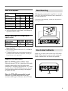
qk INTERCOM connector (minijack) and the
intercom level control
Connect the DR-100 Headset to this connector and
rotate the intercom level control with a screwdriver to
adjust the intercom level.
ql FAN ALARM indicator
A cooling fan is built into this unit. If the fan should
fail, this indicator flashes. Immediately switch off the
power, and consult your Sony dealer or service
personnel for repair. Continuing to use the unit when
the fan is defective may shorten the life of the
equipment.
Rear Panel
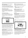
1 PROMPT VIDEO (teleprompter video signal)
IN/OUT connectors (BNC type) and 75Ω
termination switch
The IN connector accepts the teleprompter video
signal. The IN and OUT connectors are loop-through
and the signal input from the IN connector is directly
output to the OUT connector.
When no external device is connected to the OUT
connector, set the 75Ω termination switch to ON.
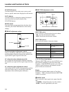
2 GENLOCK (generator lock) IN/OUT
connectors (BNC type) and 75Ω termination switch
The IN connector accepts the reference sync signal
(black burst signal or composite video signal) for
external synchronization. The IN and OUT
connectors are loop-through and the signal input from
the IN connector is directly output to the OUT
connector.
When no external device is connected to the OUT
connector, set the 75Ω termination switch to ON.
3 VBS (composite video signal) OUT 1/2
connectors (BNC type)
Use these connectors to output signals from a video
camera as composite video signals. The same signal is
output from both 1 and 2 connectors.