


23(E)
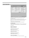
Header sequence
To specify the header sequence, select the pattern from the leftmost Pattern
box. Whilte, Black, or Checker can be selected. Then select the duration
in the leftmost Duration box. Duration can be specified between 0.5 foot
and 6.0 foot, in 0.5 foot units. Repeat this procedure to specify all the
items from left to right.
You can define up to five patterns and duration for each header.
Footer sequence
Use the procedure for defining a header sequence above to define a footer
sequence.
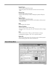
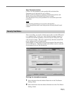
Density Patch Control column
Specifies the method of detecting the positions where the density patches
will be recorded. Set the positions where the POP signal is recorded in
order to record the density patch in the same positions. Time Code, Feet/
Frame, or POP signal can be selected as the method of detecting the
positions where the density patches will be recorded.
• When you select Time Code, type in the time you want the density patch
to be recorded in Start box. The same time unit is used as the time code
input from the TIME CODE connector.
• When you select Feet/Frame, type in the time you want the density patch
to be recorded in Start box. Feet and frame are used for time units.
• When you select POP signal, type in the start point and end point of the
recorded POP signal in Start box and End box, respectively. Feet and
frame are used as units.
If the recording of the footer density patch is unnecessary, select None as
the method of detecting the positions where the footer density patches will
be recorded.
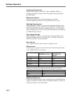
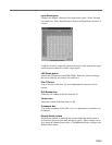
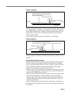
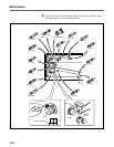
User-defined density measurement patterns
Up to five patterns each of which is 0.5 to 6.0
foot long can be selected
Film head
SDDS logo
Additional pattern (if specified)
Visual ID
Audio signal
Film tail
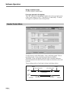
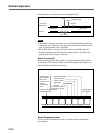
Film head
Audio signal
Visual ID
Additional pattern (if specified)
User-defined density measurement patterns
Up to five patterns each of which is 0.5 to 6.0 foot long can be selected
SDDS logo
Film tail
Short density test pattern
Short density test pattern