


15
Location and Function of Parts
Chapter 1 Overview
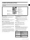
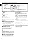
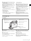
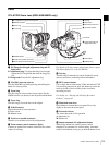
i AUDIO IN (CH-1/CH-2) (audio channel 1/2 input
selection) switches
Select the audio input signals to be recorded on audio
channels 1 and 2. The audio input is sourced as explained
below based on the position of the switches.
FRONT: The microphone connected to the MIC IN (+48
V) connector
(page 16)
WRR: A WRR-855 UHF Synthesized Tuner Unit (not
supplied)
REAR: Audio equipment connected to the AUDIO IN
CH-1/CH-2 connectors
(page 18)
The following settings can be made on the AUDIO page of
the MAINTENANCE menu.
• Audio recording format
Select either Fs48K or 32K.
• Audio reference level
Select either –12 dB or –20 dB (DSR-400/450WS), –12
dB or –18 dB (DSR-400P/450WSP).
• Audio fade-in/fade-out
Select either ON or OFF.
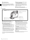
j REC TRIGGER (external VTR trigger) switch
Sets the function of the REC button on the camcorder or
the VTR button on the lens when an external VTR is
connected to the
(i.LINK) DV OUT connector (page
18). Set this switch to INT ONLY when you need to do cut
editing or dubbing using the (i.LINK) DV OUT
connector.
PARALLEL: Operates both internal and external VTRs
simultaneously.
INT ONLY: Operates the internal VTR only. External
VTR operation is performed locally.
EXT ONLY: Operates the external VTR only.
k FRONT MIC LOW CUT switch
Set to ON to insert a high-pass filter in the microphone
circuit, reducing wind noise. Normally leave the switch in
the OFF position.
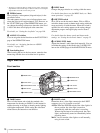
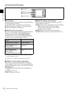
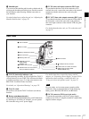
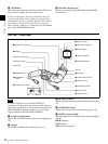
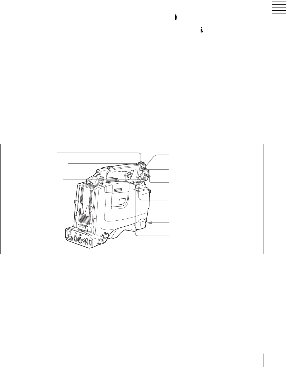
Left and upper view
Front section
a Accessory shoe
Attach an optional accessory such as a video light (page
33).
b ASSIGN 3/4 switches
You can assign the desired functions on the FUNCTION 1
page of the OPERATION menu.
For details, see “Assigning functions to ASSIGN
switches” on page 106.
c Viewfinder front-to-back position locking knob
Loosen this knob to adjust the front-to-back position of the
viewfinder
(page 30).
d Shoulder strap fitting
Attach the supplied shoulder strap (page 32).
e Viewfinder left-to-right positioning ring
Loosen this ring to adjust the left-to-right position of the
viewfinder
(page 30).
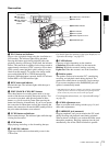
1 Accessory shoe
2 ASSIGN 3/4 switches
3 Viewfinder front-to-
back position locking
knob
4 Shoulder strap fitting
5 Viewfinder left-to-right positioning ring
6 Viewfinder fitting shoe
9 Fitting for optional microphone
holder
7 LIGHT connector
8 MIC IN connector