


44
Other Connections
Chapter 3 Connections
Other Connections
Connecting a number of camcorders
When using two or more synchronized camcorders,
connect an external sync signal to the GENLOCK IN
connector, supplying a VBS or BS signal. The camcorder
will then operate synchronized to this signal.
You can adjust the synchronization using the GENLOCK
page of the MAINTENANCE menu.
When a CBK-SD01 SDI Output Board is installed in the
DSR-450WS/450WSP, it is necessary to set REAR BNC
OUT SEL to VBS on the OUTPUT page of the
OPERATION menu.
• When a CBK-SC01 Composite Input Board (not
supplied) is installed, set REC VIDEO SOURCE to
CAM on the SOURCE SEL page of the OPERATION
menu.
• When connecting a number of camcorders and
synchronizing their time codes, wait until the reference
camcorder becomes stable (a state where a normal
picture appears on the viewfinder or the LCD monitor),
and then connect the other camcorders.
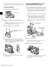
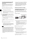
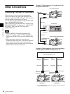
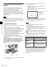
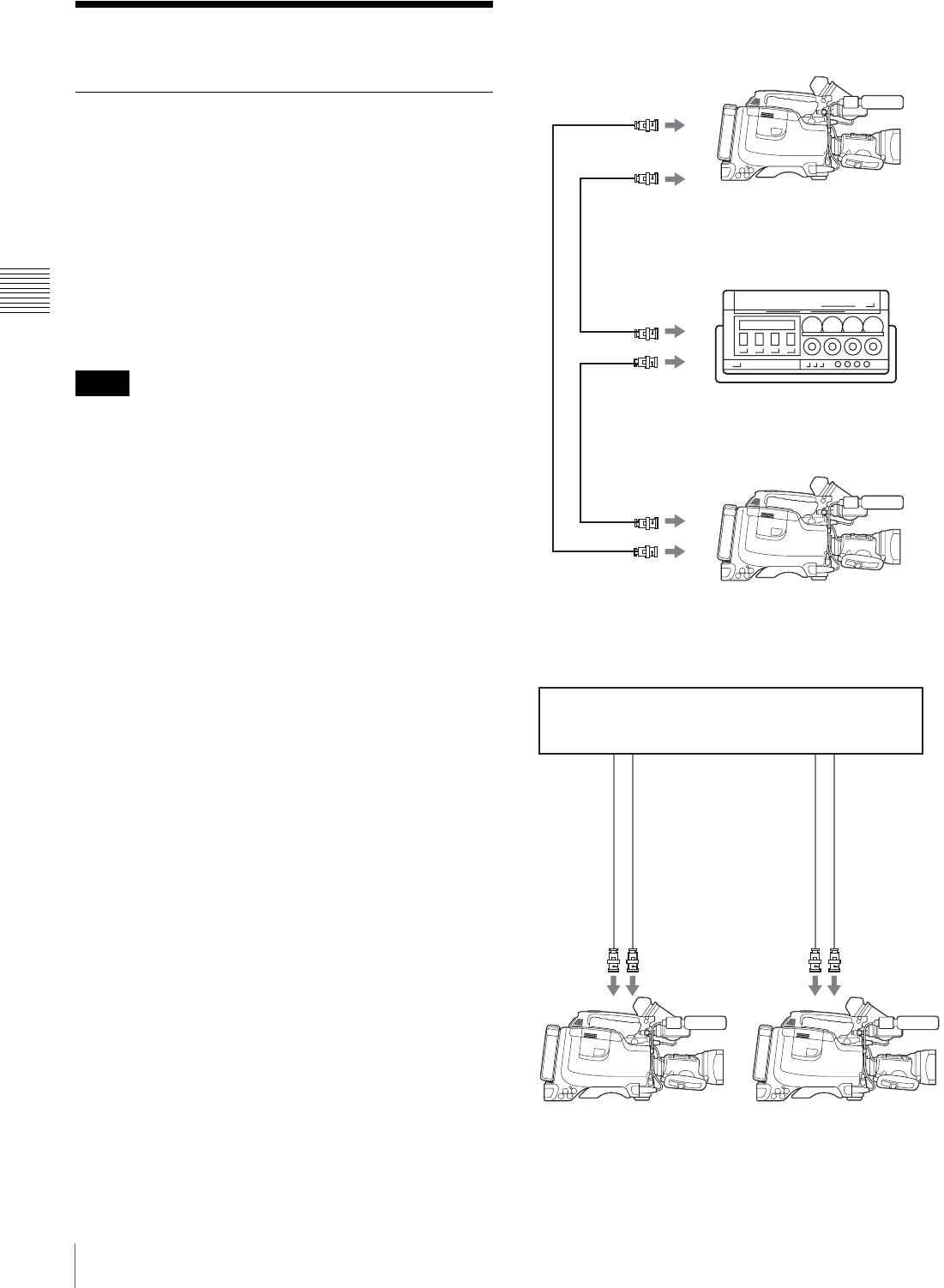
Example 1: When camcorder 2 is synchronized with
the signal of camcorder 1
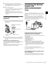
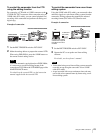
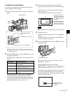
Example 2: When camcorder 1 and 2 are synchronized
with the signal of a DME switching device, etc.
Notes
DSR-450WS/450WSP
DSR-400/400P/450WS/450WSP
BNC cable
to VIDEO OUT
to MONITOR OUT
Camcorder 1
to video input
connector
to video input
connector
to MONITOR OUT/
VIDEO OUT
to GENLOCK IN
Camcorder 2
BNC cable
BNC cable
Portable VTR
DME switching device, etc.
DSR-400/400P/450WS/450WSP
DSR-400/400P/450WS/450WSP
Camcorder 1
Camcorder 2
to synchronized
signal output
connector *
to GENLOCK
IN
to
MONITOR/
VIDEO OUT
BNC cable
to video
input
connector
to GENLOCK
IN
to MONITOR/
VIDEO OUT
to synchronized
signal output
connector *
to video
input
connector
BNC cable
BNC cable
BNC cable
* Either the BB (Black Burst) signal or the Color Bar signal, etc. can be used
as a synchronized signal.