


7
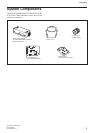
Overview
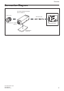
XCD-SX910CR/X710CR
XCD-SX910UV
XCD-SX910/X710
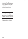
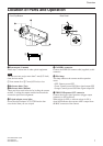
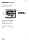
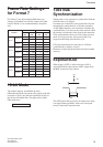
Location of Parts and Operation
1 Lens mount (C-mount)
Attach any C-mount lens or other optical equipment.
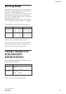
Note
The lens must not project more than 7 mm (9/32 inch)
from the lens mount.
1 Lens mount face 2 7 mm (9/32 inch) or less
2 Reference holes (Top)
3 Reference holes (Bottom)
These precision screw holes are for locking the camera
module. Locking the camera module into these holes
secures the optical axis alignment.
4 Tripod adaptor screw holes
Screw the tripod adaptor VCT-ST70I into the four
screw holes when you use a tripod.
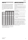
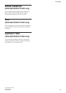
Digital Interface
34
1
2
3
TRIG IN
TRIG IN
TRIG GND
5
7
6
Rear PanelFront/Top/Bottom
1
2
5 CAMERA connector
Connect the IEEE1394 camera cable (supplied) to this
connector.
6 Pilot lamp
This lamp indicates the camera module operation
states:
OFF: Camera power OFF
Green: Camera power ON/Video signal output OFF
Orange: Camera power ON/Video signal output ON
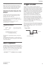
7 TRIG IN/Exposure OUT connector
Connect the trigger signal generator (trigger output
connector) to this connector.
When trigger is OFF, or software trigger is ON, a
signal that indicates the exposure time is output from
the BNC connector of the camera.