


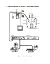
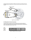
2.6 Connections
• Connecting to the RS485/ 422
The dome camera can be controlled remotely by an external device or control system, such as a
control keyboard, using RS485 half-duplex , RS422 duplex or simplex serial communications
signals. Connect Marked Rx+, Rx- to Tx+ and Tx- of the RS485 control system.
If control system is RS422, connect Rx+(Tx+), Rx+(Tx-) and Rx+, Rx- of the dome camera to
Tx+, Tx- and Rx+, Rx- of the control device respectively.
• Connecting Video out connector
Connect the video out(BNC) connector to the monitor or video input.
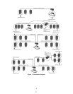
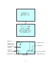
• Connecting Alarms
AL1 to 8 (Alarm In)
You can use external devices to signal the dome camera to react on events. Mechanical or
electrical switches can be wired to the AL (Alarm In) and GND (Ground) connectors.. See
Chapter 3 — Program and Operation for configuring alarm input.
GND (Ground)
NOTE: All the connectors marked GND are common.
Connect the ground side of the Alarm input and/or alarm output to the GND connector.
NC(NO)1 TO 4 (Normal Close or Normal Open : Alarm Out)
The dome camera can activate external devices such as buzzers or lights. Connect the device to
the NC(NO) (Alarm Out) and COM (Common) connectors. See Chapter 3 — Program and
Operation for configuring alarm output.
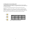
• Connecting the Power
Connect the power of AC 24V 850mA to the dome camera.
Use certified / Listed Class 2 power supply transformer only.
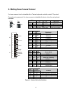
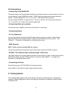
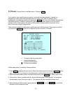
2.7 Getting Started
Once installed apply power to the dome camera. The dome camera will start a configuration
sequence. When configuration is done, the following information is displayed on the keyboard
controller’s LCD
9