


Chapter 5: Advanced Serverboard Setup
5-15
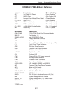
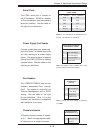
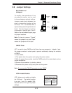
Chassis Intrusion
A Chassis Intrusion header is located
at JL1. Attach the appropriate cable
to inform you of a chassis intrusion.
Chassis Intrusion
Pin Defi nitions (JL1)
Pin# Defi nition
1 Intrusion Input
2 Ground
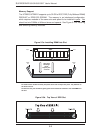
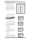
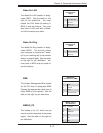
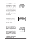
Fan Headers
The X7DBR-3/X7DBR-E has fi ve fan
headers, designated Fan1 through
Fan5. Fan speed is controlled via
Thermal Management with a BIOS
setting. See the table on the right
for pin defi nitions. (Pins 1-3 on the
headers are backward compatible
with traditional 3-pin fans.)
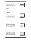
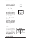
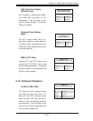
Serial Ports
The COM1 serial port is located on
the IO backplane. COM2 is a header
on the serverboard (see serverboard
layout for location). See the table on
the right for pin defi nitions.
Note: Pin 10 is included on the header but not on
the port. NC indicates no connection.
Serial Port Pin Defi nitions
(COM1, COM2)
Pin # Defi nition Pin # Defi nition
1 DCD 6 DSR
2 RXD 7 RTS
3 TXD 8 CTS
4 DTR 9 RI
5 Ground 10 NC
Fan Header
Pin Defi nitions
(Fan1-5)
Pin# Defi nition
1 Ground (Black)
2 +12V (Red)
3 Tachometer
4 PWM Control
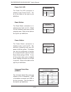
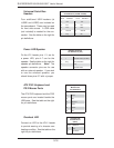
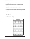
Power Supply Fail Header
Connect a cable from your power sup-
ply to the Power Fail header to provide
you with warning of a power supply
failure. The warning signal is passed
through the PWR_LED pin to indicate
a power failure. See the table on the
right for pin defi nitions.
Power Supply Fail Header
Pin Defi nitions (JPWF)
Pin# Defi nition
1 P/S 1 Fail Signal
2 P/S 2 Fail Signal
3 P/S 3 Fail Signal
4 Alarm Reset
Note: This feature is only available when using
redundant Supermicro power supplies.
Note: Currently only 3-pin control is supported
(no PWM).