


5-18
SUPERSERVER 6015B-3/6015B-T User's Manual
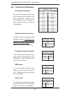
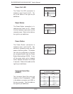
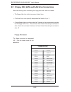
JLAN1/2 (Ethernet Ports)
Two Ethernet ports (designated JLAN1
and JLAN2) are located beside the
VGA port on the I/O backplane. These
ports accept RJ45 type cables.
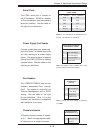
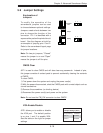
SGPIO
The two headers labeled SGPIO1 and
SGPIO2 are for SGPIO (Serial Gen-
eral Purpose Input/Output). SGPIO
provides a bus between the SAS/SATA
controller and the SAS/SATA drive
backplane to provide SAS/SATA en-
closure management functions. Con-
nect the appropriate cables from the
backplane to the SGPIO1 and SGPIO2
headers to utilize SAS/SATA manage-
ment functions on your system.
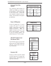
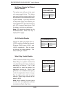
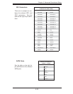
Alarm Reset (JAR)
The system will notify you in the event
of a power supply failure. This feature
assumes that Supermicro redundant
power supply units are installed in the
chassis. Connect a microswitch to the
JAR header to disable the power supply
fail alarm. Note: this header is unused
with the 6015B-3/6015B-T.
Alarm Reset
Pin Defi nitions (JAR)
Pin# Defi nition
2 +5V
1 Ground
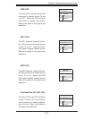
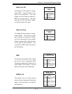
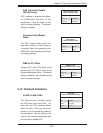
Compact Flash Card PWR
Connector
A Compact Flash Card Power Connector
is located at JWF1. For the Compact
Flash Card to work properly, you will
fi rst need to connect a power cable to
JWF1 and correctly set the Compact
Flash Jumper (JCF1).
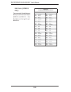
SGPIO Header
Pin Defi nitions (SGPIO1, SGPIO2)
Pin# Defi nition Pin # Defi nition
1NC 2NC
3 Ground 4 Data
5 Load 6 Ground
7NC 8NC
Note: NC indicates no connection.