


4
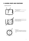
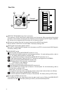
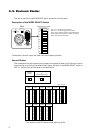
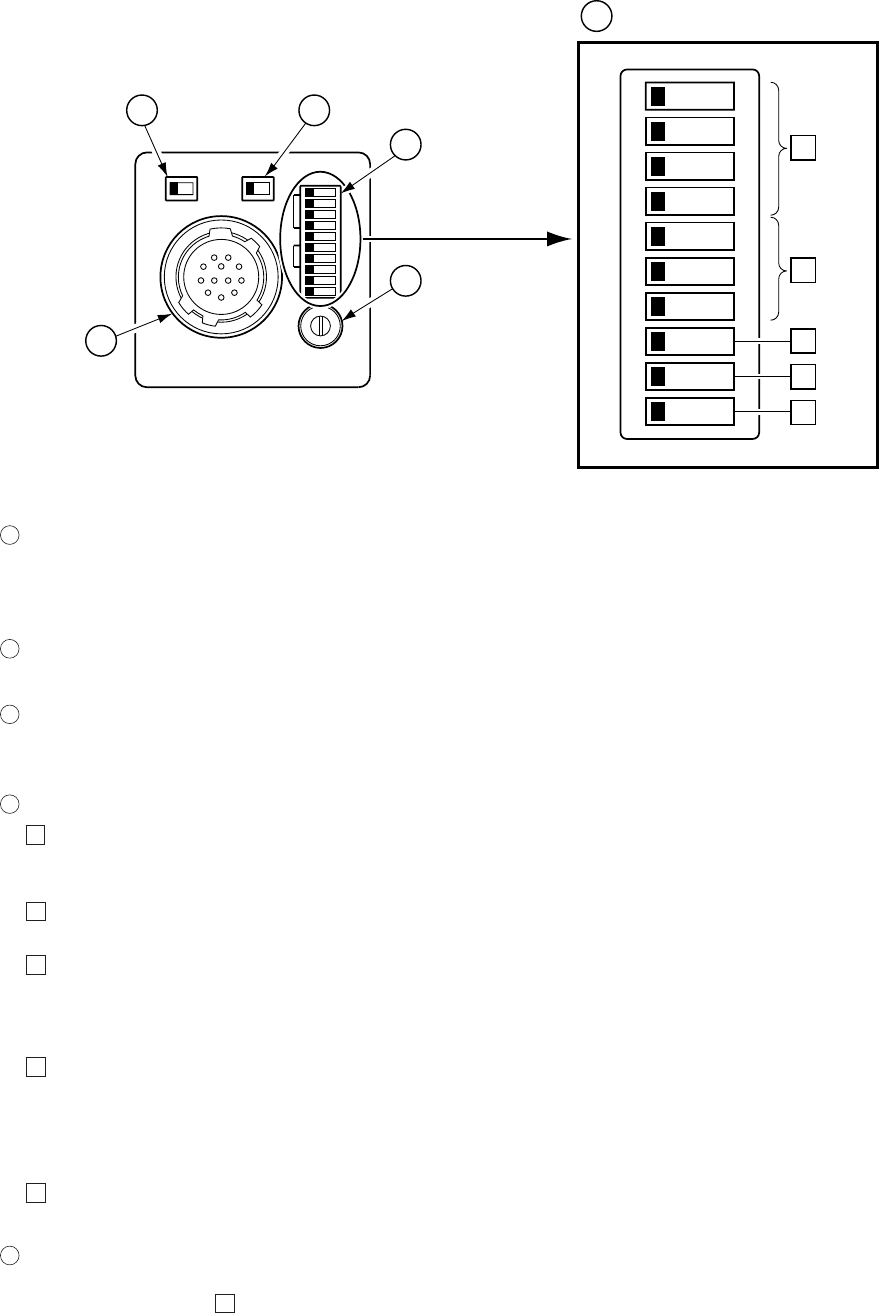
Rear Side
ON OFF
EXT
INT
HD/VD
75Ω
SHT
TRG
M.G
MIN MAX
M GAIN
VIDEO OUT
DC IN/SYNC
P.S
Enlarged
1
VIDEO OUT DC IN/SYNC plug (12-pin connector)
This receives +12 VDC, and sends a video signal from the camera. When a synchronizing signal
generator is connected to this plug and an external synchronizing signal (HD/VD signal) is applied,
the camera can be operated synchronously with the external signal.
2
75Ω terminal switch (Terminal of external synchronizing HD/VD input signal)
Set this switch to OFF when not terminated. The factory setting is ON.
3
HD/VD signal input/output selector switch
Set to INT to output the HD/VD signals from the camera, and EXT to input external HD/VD signals.
The factory setting is EXT.
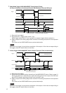
4
MODE SELECT switch
1
Shutter speed setting (MODE SELECT switch bit 1 to 4)
Set to the shutter speed suitable for the shooting conditions. For each setting position, refer to
P. 8. The factory setting position is shutter OFF.
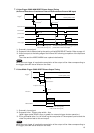
2
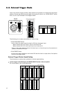
Reset restart/External trigger mode setting (MODE SELECT switch bit 5 to 7)
For each setting position, refer to P. 9 to 14. The factory setting position is NORMAL.
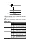
3
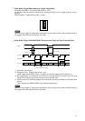
Trigger polarity setting (MODE SELECT switch bit 8)
Selects the polarity of an externally inputted trigger.
OFF: Positive ON: Negative
The factory setting position is OFF.
4
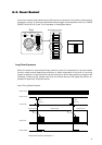
Partial scanning mode setting (MODE SELECT switch bit 9)
Use Pin 9 (PART input) of the 12-pin connector on the rear panel. For the mode setting, refer to
P. 6. The factory setting is OFF.
(PART input; H: 2 to 5V, L: 0 to 0.4V)
During partial scanning mode, 134 lines are output to the screen center (frame rate 180 fps).
5
Gain selector switch setting (MODE SELECT switch bit 0)
This switch selects the modes OFF (fixed) or ON (manual). The factory setting is OFF (fixed).
5
Manual gain (M GAIN) control knob
This adjusts the gain of a video signal when the gain mode is set to ON by the MODE SELECT
switch bit 0 on step
5
. The factory setting is the fully counterclockwise position.