


29
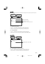
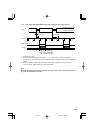
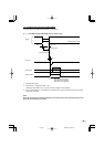
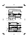
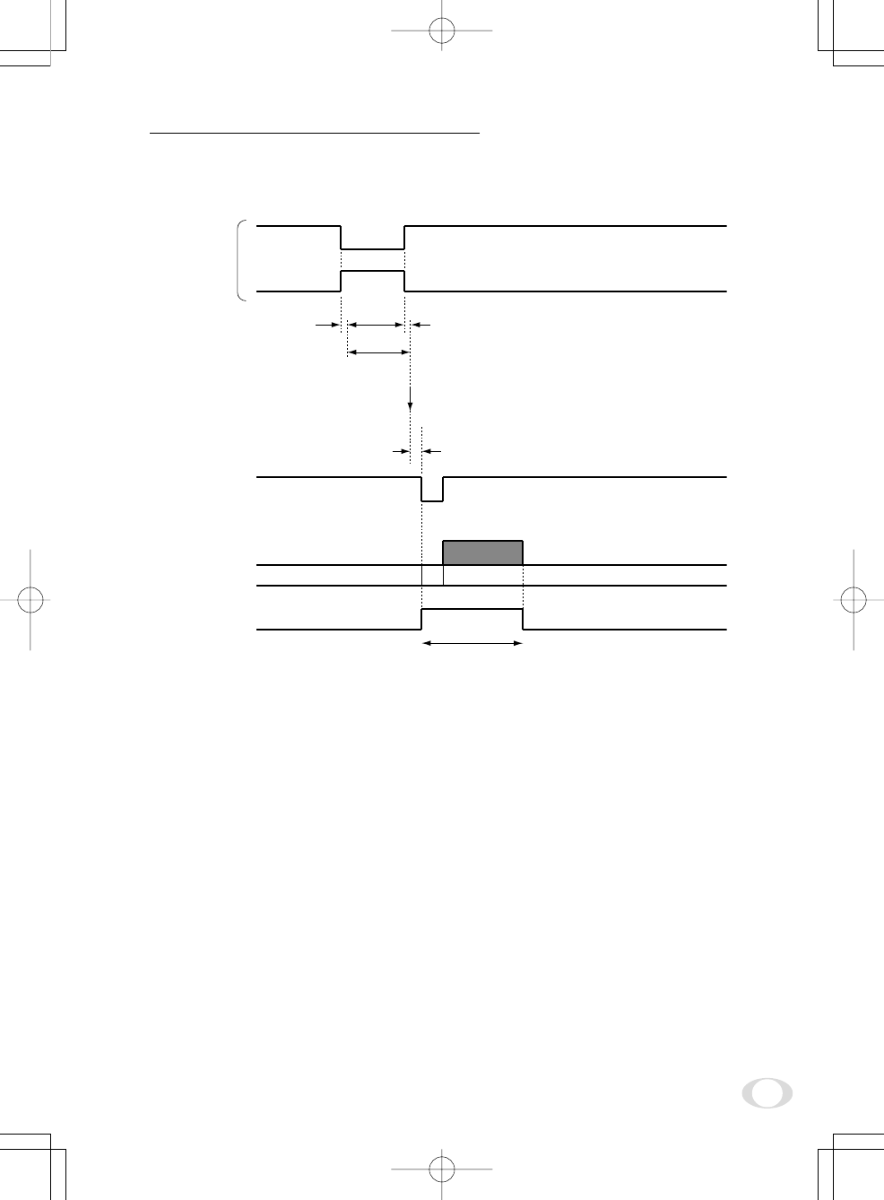
( 4 ) PW SR (Pulse width trigger SYNC-RESET)
The trgger input to the RGB terminal develops 1 frame images.
(4. 1) 1 Pulse Width Trigger SYNC-RESET Picture Output Timing
*1: Externally input signal
*2: Exposure time = Trigger pulse width + 6 µs
(Valid trigger pulse width is 2 µs or greater for external trigger shutter operation.)
*3: VD is generated after 0 to 1H following the completion of the exposure period and the video is synchro-
nized to this and output.
Note:
When the next trigger is input before completion of the output of the video corresponding to the trig-
ger, there will be an effect on the video.
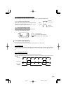
About 1 µs
About 7 µs
Exposure completion
0 to 1H
Video output
VIDEO INDEX
VD OUT
*
3
Trigger*
1
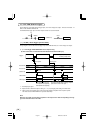
796H (Partial scanning OFF)
387H (Partial scanning 60fps)
258H (Partial scanning 90fps)
Negative polarity mode
Positive polarity mode
Exposure period*
2
2004.03.24, 0:59 PMPage 29