


6
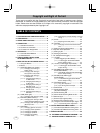
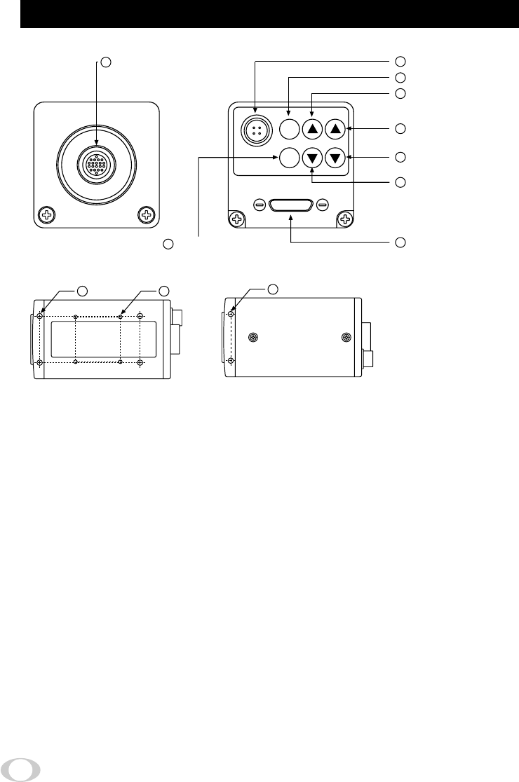
3. NAMES AND FUNCTIONS
1
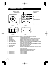
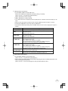
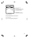
Camera cable for ‘IK-TF9H’ terminal Where the camera cable for ‘IK-TF9H’ is connected.
2
DISP button Used when switching the display.
3
PAGE button Used when switching to the menu and when selecting the menus.
4
MENU UP button Select the function to be confirmed or changed on the menu.
5
MENU DOWN button Select the function to be confirmed or changed on the menu.
6
DATA UP (AWB) button Changes the value of the function selected by the MENU (UP/DOWN)
button. (Also used when using AWB.)
7
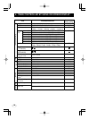
DATA DOWN ABB button Changes the value of the function selected by the MENU (UP/DOWN)
button. (Also used when using ABB)
8
DC IN 12V terminal Accept a DC power input (12V).
9
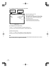
RGB terminal 8-bit RGB, digital signal, and sync signal are output in the Camera
Link format.
Trigger signal is input.
Mode switching signal for partial scanning is input.
Accepts serial communication control signal.
!
Mounting holes M3 Used to fix the camera.
"
Mounting holes M2 Used to fix the camera.
#
Mounting holes M3 Used to fix the camera.
DISP
PAGE
DC IN 12V
MENU
DATA
(AWB)
1
8
2
4
6
7
5
9
3
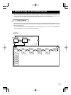
Camera cable for
‘IK-TF9H’ terminal
DIGITAL terminal
DISP button
PAGE button
[ Rear ][ Front ]
MENU UP button
MENU DOWN button
DATA UP (AWB) button
DATA DOWN button
DC IN 12V terminal
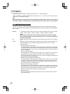
12
10 11
[ Bottom ] [ Top ]