


7
4. CONNECTION
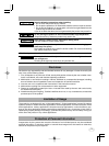
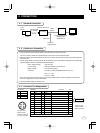
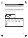
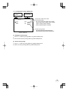
4. 1 Standard Connection
DC IN 12V
Camera cable
for IK-TF9U
IK-TF9U
Camera control unit
Cable
(option)
(option)
IK-TF9H
(option)
Lans
(option)
Frame grabber board,
image process
equipment etc.
Monitor
DC power
supply (option)
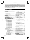
DC IN 12V
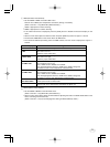
Connector used:
HR10A-7R-4PB
(HIROSE electronics
Co. Ltd) or equivalent.
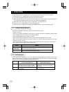
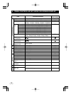
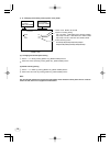
DIGITAL Function I/O
1 +12V
1
2 +12V
2
3 GND
3
4 GND
4
5
6
7
8
9
10
11
12
13
GND
X0-
X1-
X2-
Xcllk-
X3-
SerTC+
SerTFG-
CC1-
CC2+
CC3-
CC4+
GND
14
15
16
17
18
19
20
21
22
23
24
25
26
–
O
O
O
O
O
I
O
I
I
–
–
–
GND
X0+
X1+
X2+
Xcllk+
X3+
SerTC-
SerTFG+
CC1+
CC2-
CC3+
CC4-
Serial communication control (RXD)
Serial communication control (TXD)
Trigger pulse input
Partial scanning control
NC
NC
GND
1
113
26 14
2
4
3
Connector used:
12226-51000-00
(3M) or equivalent.
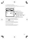
4. 2 Cautions on Connection
• Only use optional camera head model # IK-TF9H with this camera controller.
The use of another head may cause damage to the control unit and camera head.
• When connecting the camera cables, be sure to turn off the camera control unit and any other equipment
connected to it.
•For DC power supply connecting to DC IN 12V terminal, use UL listed and/or CSA approved ungrounded
type AC adaptor with the specifications described below.
Power supply voltage : 12V DC±10%
Current rating : More than 830mA, Less than2.5A
Ripple voltage : Less than 50mV(p–p)
Connector : HR10A–7P–4S by HIROSE electronics Co. Ltd
Pins 1, 2 : 12V
Pins 3, 4 : GND
• If the securing screw on the connector of the camera cable loosens, noise may appear on the screen.
Be sure to tighten the connector completely.
•Use the standard cable for Camera Link.
4. 3 Connector Pin Assignments