


- 9 -
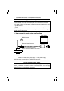
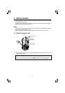
6-2 Installing the Camera Unit
6-2-1
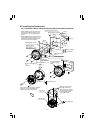
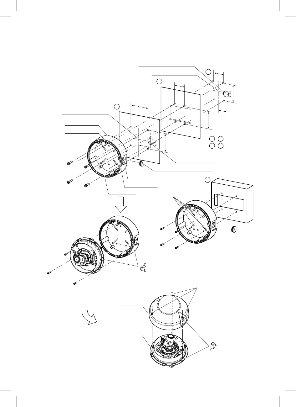
Installation to Wall or Ceiling with Mounting Base (Surface Mount Installation)
A
B
C
D
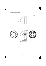
Mounting Base
Mounting Base center
Drain groove
Mounting Base center
Drain groove
A
C
B
D
, Wall or Ceiling
, Junction Box
Align to this mark.
In case of using the
variable mounting
holes
Align to this mark.
Rear cable hole
Cable exit
(sideway)
Screws (not supplied)
x4
Fix firmly.
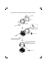
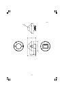
Top Cover
Camera Base
Screws
x3
Mount camera base with three supplied
screws A. (Longer screw(M4x16))
Tighten and lock the screws firmly.
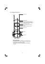
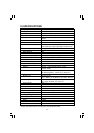
Cable access hole
ø27 mm
Cable access hole ø27 mm
With female screw for piping
55 mm
55 mm
83.5 mm
83.5 mm
85 mm
85 mm
46 mm
46 mm
7
7
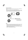
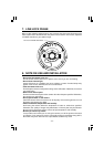
• When installing the camera unit on the
wall, mount it with the drain groove on
the downside. Do not block the drain
groove.
• When installing the camera unit outdoor,
make waterproof for the cables. The
camera body is water-resistant but the
brackets are not water-resistant.
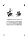
Mount the top cover (the
assembly of the dome
cover) and secure it firmly
with three security screws
by the supplied special
hexangular wrench.