


141414
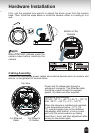
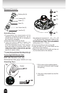
1. Disassemble the components of the
waterproof connector into parts (A) ~ (E) as
shown above. And Hex Nut is including in
the accessory separately.
2. Place the screw nut (E) as shown.
3. Feed the power cables through the
waterproof connector (F --> E --> D --> B -->
A) as the illustration shows. Then connect
the power cables to the power source. Note:
There are 8 holes on the seal (D), and the
widest holes with a crack on the side are
specic for power cables.
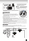
4. If you have external devices such as
sensors and alarms, feed the cables through
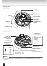
Assembling Steps
Sealing Nut (A)
Housing (B)
Seals (C)
Seal (D)
Screw Nut (E)
Hex Nut (F)
Waterproof Connector
(A)
(B)
(D)
(E)
(F)
the waterproof connector (F --> E --> D --> B
--> A) as previously described. Refer to the
pin denition to connect them to the general
I/O terminal block. Note: The recommended
cable gauge is 2.0 ~ 2.8 mm.
5. Push the seal (D) into the housing (B).
6. Insert the seals (C) into unused holes on the
seal (D) to avoid moisture.
7. Secure the sealing nut (A) tightly and hex nut
(F) from the bottom of the camera.
1
2
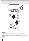
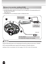
RJ45 Cable Dimension (unit: mm)
2. Strip part of the sheath from the Eth-
ernet cable.
1. Drill a hole on the supplied gasket
and insert an Ethernet cable through
the opening.
Gasket
Assembling Steps:
Recommended cable gauge: 24AWG (0.51 mm)
Connecting RJ45 Ethernet Cable