


15
NOTE
4
3
o
O
g
B
b
G
br
BR
1
2
3
4
5
6
7
8
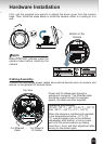
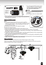
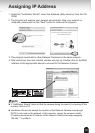
o: white/orange stripe
O: orange solid
g: white/green stripe
B: blue solid
b: white/blue stripe
G: green solid
br: white/brown stripe
BR: brown solid
3. You will need an RJ45 crimping tool to
attach the Ethernet wires to a connec-
tor. When done, connect the cable to
the camera’s Ethernet socket .
l
RJ45 crimping tool and plug are not
included.
l
Use Category (Cat) 5e or higher cable.
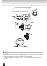
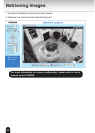
4. Press the Ethernet cable into the routing path at the bottom of
the camera so that the cable will not get in the way when the
mounting plate is attached.
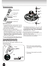
Ceiling and Wall mount
Notes:
l
The included screws and anchors are used to install the
camera to a solid surface. (e.g. concrete) If installing on loose
or thin material surfaces , use the appropriate anchors (not
included) with the screws.
l
Generally point the status LED towards the object.
l
Install the camera securely.
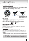
1. Attach the supplied alignment sticker to the ceiling or wall.
2. Using the circle marks on the sticker, drill four pilot holes (Ø0.19inch×1.02inches(D)
(Ø4.8mm×26mm(D))) symmetrically on each side into the ceiling. Then hammer the four sup-
plied plastic anchors into the holes.
3. Through four holes on the mounting plate, insert the supplied screws into the corresponding
holes and secure the mounting plate with a screwdriver.
4. Drill a hole (Ø1.0inch(Ø25mm)) in the triangular cutout of mounting plate, and lead the cables
through this hole. (A)
5. Align the three mounting holes of the camera with the three studs on the mounting plate and
tighten them with a supplied torx wrench securely.
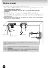
Cable installation
If possible, lead all cables behind the camera body through a wall or ceiling.
If this is not possible, remove the side opening cover with a screwdriver (B), and to route the
cables through the side. (Refer to the page 11.)
1
5
A
2
3