


VIVOTEK
6 - User's Manual
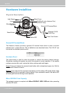
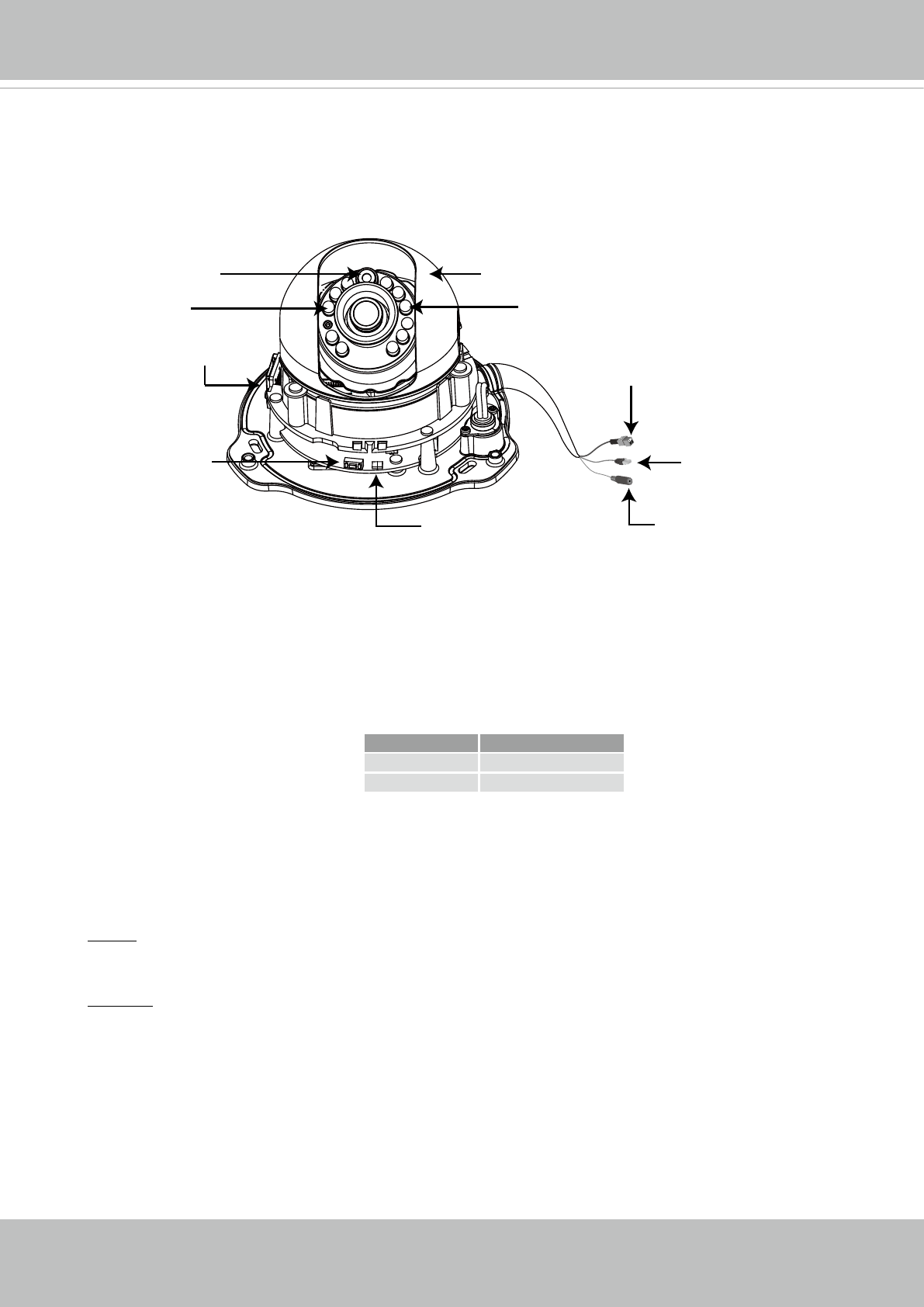
Physical Description
General I/O Terminal Block
This Network Camera provides a general I/O terminal block which is used to connect
external input / output devices. The pin denitions are described below. The 24V AC can
be used as an alternate power source.
Hardware Reset
The reset button is used to reset the system or restore the factory default settings.
Sometimes resetting the system can return the camera to normal operation. If the system
problems remain after reset, restore the factory settings and install again.
Reset: Press and release the recessed reset button with a straightened paper clip. Wait for
the Network Camera to reboot.
Restore: Press and hold the recessed reset button until the status LED rapidly blinks. Note
that all settings will be restored to factory default. Upon successful restore, the status LED
will blink green and red during normal operation.
Micro SD/SDHC Card Capacity
This network camera is compliant with Micro SD/SDHC 16GB / 8GB and other preceding
standard SD cards.
Pin Name
+ Digital Input +
- Digital Input -
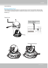
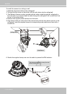
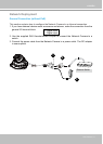
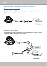
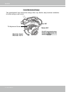
Hardware Installtion
Lens
Reset Button
General I/O Terminal Block
IR LEDs (8 units, distance 10m)
(FD8134V only)
Status LED
Light Sensor
MicroSD/SDHC
Card Slot
Black Cover
Ethernet 10/100
RJ45 Plug
Power Cord Socket