


- 5 -
Installation
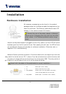
Hardware installation
All necessary accessories can be found in the product
package except for the Ethernet cable that depends on the
user’s environment. The Ethernet cable should meet UTP
category 5 that cannot exceed 100 meters.
Connect the jack of the power adapter to Network
Camera prior to plugging the utility end into the utility
power socket. It will reduce accidental electric surge
shock.
As soon as the power adapter is plugged into the utility socket, the front LED will switch
between green and red for several times. After passing the self-test, the LED will shut
off and Network Camera will standby for software installation. Otherwise refer to
Appendix A for troubleshooting.
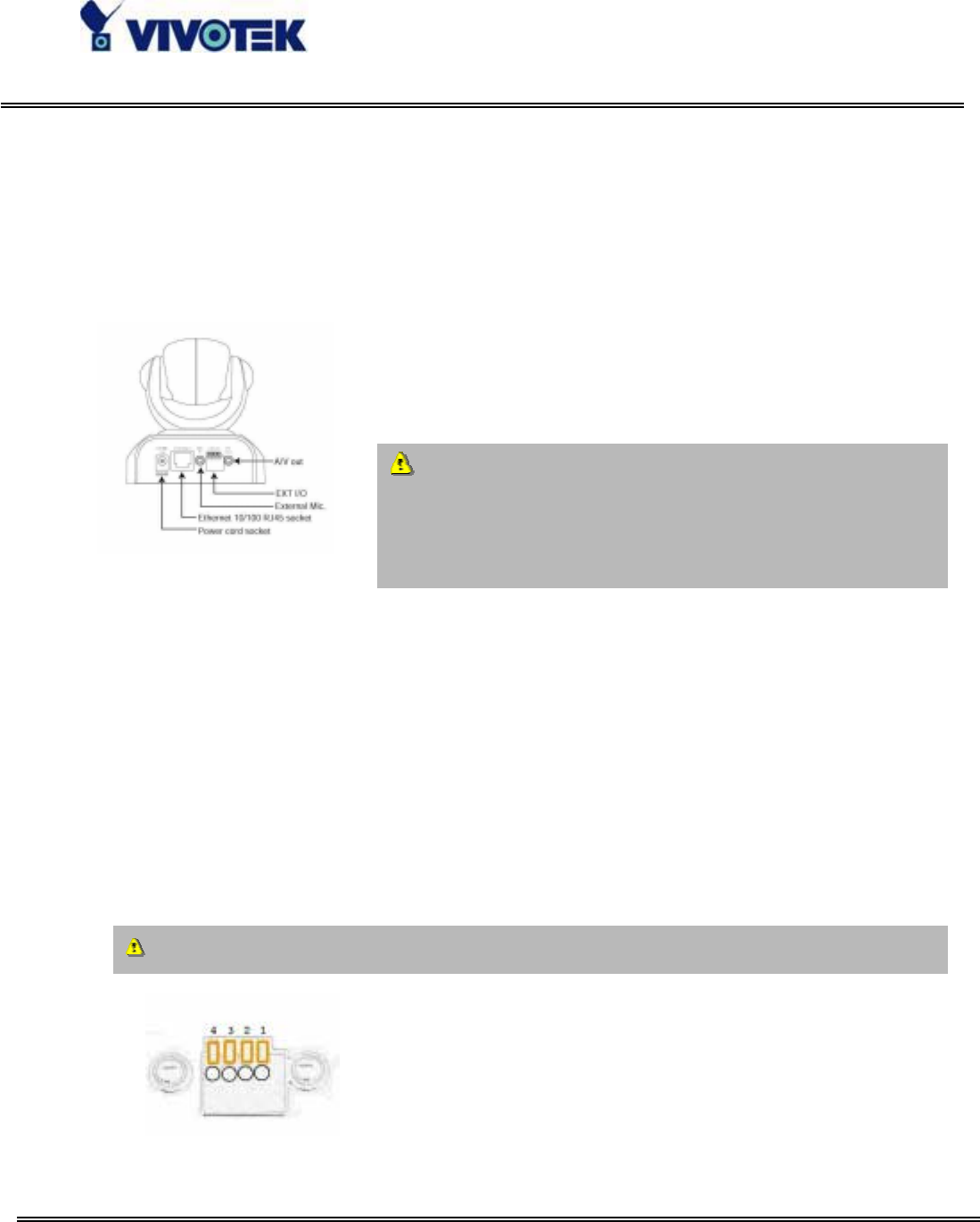
Network Camera provides a general I/O terminal block with one digital input and one
relay switch for device control. Pin 1 and pin 2 can be connected to an external sensor and
the state of voltage will be monitored from the initial state 'LOW'. The relay switch of
pin 3 and pin 4 can be used to turn on or off the external device.
Consult with the dealer of the peripherals for correct installation.1
1 DI+ INPUT (Max. 50mA, 12VDC)
2 DI- INPUT (Initial state of DI is low)
3 SW_COMMON OUTPUT (open from SW_OPEN at initial state)
(close with SW_OPEN when set DO to ON)
4 SW_NOPEN OUTPUT (Max. 1A, 24VDC or 0.5A, 125VAC)
www.vivotek.com
T: 886-2-22404099
F: 886-2-22404097