www.vivotek.com
T: 886-2-82455282
F: 886-2-82455532
To install in Ethernet
Make sure the Ethernet is firmly connected to a switch hub. After attaching the
Ethernet cable plug in the power adapter. If the LED turns out to be steady green after
self-test, go to next paragraph “Software Installation”. If the Ethernet is not available,
the Network Camera will switch to wireless LAN mode.
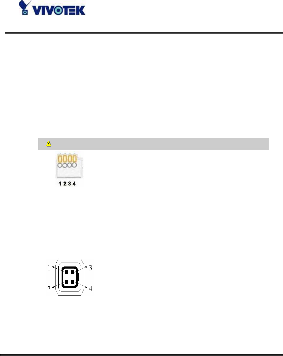
The Network Camera provides a general I/O terminal block with one digital input and
one relay switch for device control. Pin 3 and Pin 4 can be connected to an external
sensor device and the state of voltage can be monitored from the initial state 'LOW'.
The relay switches Pin 1 and Pin 2 can be used to turn on or off an external device.
Consult with the dealer of the peripherals for correct installation.
1 SW_COMMON OUTPUT (open from SW_OPEN at initial state)
(close with SW_OPEN when set DO to ON)
2 SW_NOPEN OUTPUT (Max. 1A, 24VDC or 0.5A, 125VAC)
3 DI+ INPUT (Max. 50mA, 12VDC)
4 DI- INPUT (Initial state of DI is low)
The Network Camera also provides the auto iris lens connector. If the auto iris lens is
used, AES option in CCD settings must be turned OFF. And you also have to select
VIDEO drive or DC drive lens by select correct iris mode in CCD settings. The pin
assignment of the auto iris lens connector is as follows.
Video Drive DC Drive
1. Ground, Shield 1. Driver -
2. Not used 2. Driver +
3. Video signal 3. Damp +
4. Power source 4. Damp -


