


BPS-120 User’s Guide
12
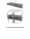
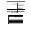
2.3 Attaching Power Cables and Connector
Definition
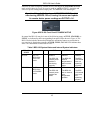
The BPS-120 includes power connections for up to six (6) external devices. The
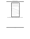
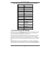
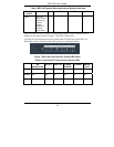
rear connector pin-out diagram and power signal descriptions are shown in the
following Figure 5, and Table 1 for OUTPUTs (1-6). Backup power is supplied by
inserting power cables into any of the OUTPUTs (1-6) on the rear panel of the BPS-
120 and into the corresponding power input connector of device(s) such as switches or
routers. The power connector cables may be inserted only one way. There is no need to
worry about inserting the power cables incorrectly as they are keyed for one position.
Backup power for externally connected devices is supplied based upon output port
priority, with OUTPUT 1 having the highest priority. That is, an external device
connected to OUTPUT 1 has backup power priority over devices connected to
OUTPUTs 2-6. OUTPUT 2 has backup power priority over devices connected to
OUTPUTs 3-6, etc.
To turn the BPS-120 on, connect the power line cord to a 100/240 VAC power outlet
and move the rocker switch on the rear panel from the “0” to “1” position. The
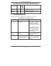
STANDBY, PWR, TEMP, and FAN LEDs will then light on the front panel. If they
do not light up see Table 5 for troubleshooting information.
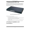
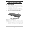
Figure 4 BS-120 Rear Panel Showing OUTPUT Port Power Connections