


BPS-120 User’s Guide
15
should be lit) when connecting external devices, then toggle the STANDBY/ACTIVE
mode switch (shown in Figure 6) to active mode to update OUTPUT 1-6 priority and
sense new power readings at the output ports. The ACTIVE LED should light.
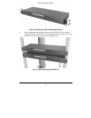
You should toggle the front panel STANDBY/ACTIVE switch
after turning the BPS-120 on, forcing it to sense and update
its remote device power readings on OUTPUTs 1-6.
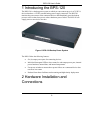
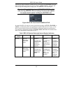
Figure 6 BPS-120 Front Panel STANDBY/ACTIVE
In general the BPS-120 may be in one of the following states: ACTIVE, STANDBY, or
FAULT, as indicated by their corresponding front panel LEDs shown in Figure 6. The
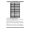
BPS-120 also includes advanced self-diagnostic monitoring features to ensure that its
own circuitry is functioning normally; the PWR, TEMP, and FAN LEDs indicate these
states. This information is described in Table 2.
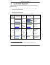
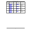
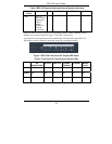
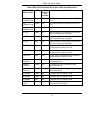
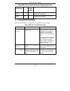
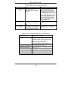
Table 2 BPS-120 System States and Internal System Indicators
BPS-120
STATE
PWR TEMP FAN
ACTIVE On: The
BPS-120 is
in ACTIVE
mode.
GREEN:
The BPS-120
internal power
module is
functioning
normally.
GREEN:
The BPS-120
internal
temperature is
within normal
limits.
GREEN:
The BPS-
120 internal
fans are
operating
normally.
STANDBY On: The
BPS-120 is
in STANDBY
mode.
RED:
The BPS-120
internal power
module has
failed.
RED:
The BPS-120
has an internal
over-
temperature
problem.
RED:
The BPS-
120 internal
fan(s) are
not
operating
properly.