


BPS-120 User’s Guide
14
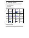
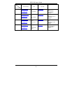
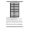
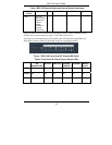
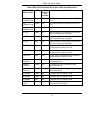
Table 1 BPS-120 OUTPUT Port Connector(s) (1-6) Pin Definition
PIN NUMBER DESIGNATION
1 GND
2 N/A
3 12V
4 12V
5 12V
6 12V
7 GND
8 GND
9 N/A
10 BPS present
11 BPS Status0
12 BPS Status1
13 Power good
14 GND
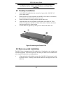
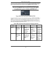
2.4 Front Panel and LED Displays
The BPS-120 defaults to STANDBY mode when the BPS-120 is switched on. Depress
the front panel dual function STANDBY/ACTIVE switch to place the BPS-120 in
active mode, capable of supplying power to remote devices.
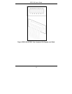
System and remote power status information are shown on the front panel of the BPS-
120 using two groups of LED displays: the first group shown in Figure 6 monitors
internal BPS-120 parameters and the system mode (standby/active), the second group of
LEDs shown in Figure 7 shows status information for each of the six power OUTPUT
ports.
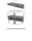
Enabling backup power to any of six external devices is as simple as connecting the
(supplied) system power cables from each OUTPUT 1-6 on the back panel of the BPS-
120 to external devices. Be sure the BPS-120 is in standby mode (the STANDBY LED)