Model D2424 Reference Manual (Names and Functions)
18
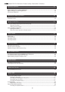
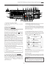
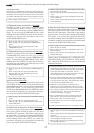
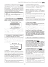
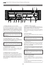
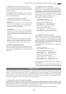
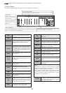
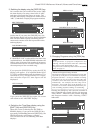
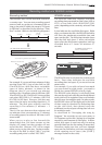
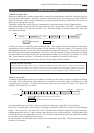
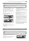
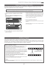
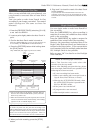
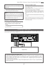
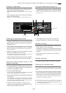
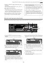
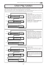
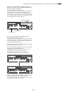
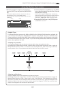
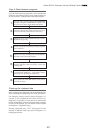
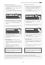
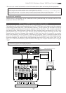
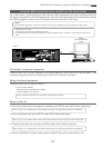
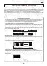
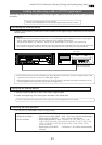
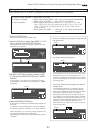
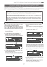
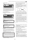
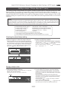
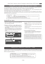
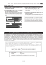
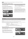
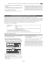
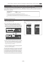
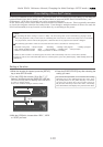
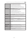
Rear panel section
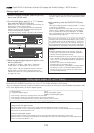
7. Optional Panel
The additional installation panel for the optional
Model 8345 (TC/SYNC card x1) or Model 8350 (AES/
EBU card x 1). Normally, it can be used with the
panel remained installed.
<Note>
Installation of the option must be done by our Fostex
Service Station. For details, please inquire at your nearest
Fostex Service Station.
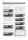
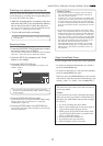
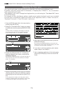
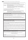
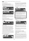
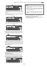
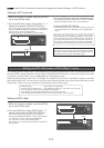
1. Analog Input jack (connector: PHONE)
External analog audio signals to the D2424 are input
here. These are connected, for example, to external
mixer's group out (BUSS OUT) connectors. As signals
applied to [INPUT 1-8] are simultaneously sent to
tracks 1-8, 9-16 and 17-24, tracks for recording must
be selected via the [RECORD TRACK] select key.
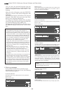
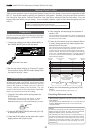
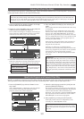
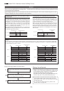
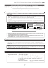
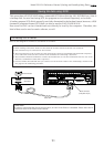
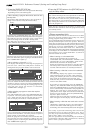
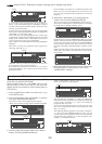
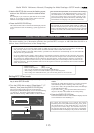
6. AC IN connector
The power cable packaged with this recorder is
connected here.
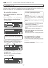
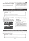
5. REMOTE THRU connector
RS-422 control signal (SONY 9PIN PROTOCOL or
Fostex System Exclusive Message) input from the
[REMOTE INPUT] connector is output here.
This is connected to the second recorder REMOTE
INPUT when controlling a multiple number of
recorders.
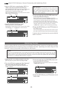
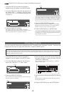
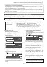
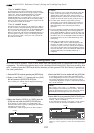
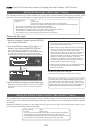
4. REMOTE INPUT terminating switch
This REMOTE INPUT terminating switch (100Ω) is
switched ON for normal use of an inputted RS-422
control signal into the [REMOTE INPUT] connector.
When controlling a multiple number of recorders,
the last one only is switched ON; the others are
switched OFF.
3. REMOTE INPUT connector
External RS-422 control signal (SONY 9PIN
PROTOCOL or Fostex System Exclusive Message) is
input here to control this recorder.
<Note>
Always plug the power cable to the recorder before
plugging the cable into the wall outlet.
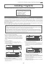
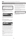
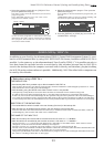
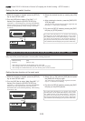
8. SCSI connector [SCSI]
(connector: half-pitch 50-pin)
Connect a backup SCSI device to SAVE/LOAD data.
Up to one SCSI devices can be connected to the SCSI
connector.
* Refer to page “
91
” for more details on SAVE/LOAD
using a SCSI device.
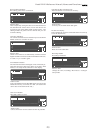
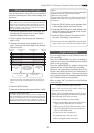
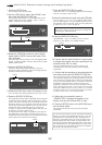
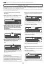
<Note>
Analog input/output can be switched for balance/
unbalance via the SETUP mode. At initial setup, it is set
for unbalance.
• For functions at installation of the optional Model
8345, please refer to [References] on the last page of
this manual.
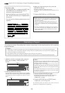
2. Analog Output jack (connector: PHONE)
Analog audio signals (Channels 1-24) from D2424
are output here. For example, this is connected to
the external mixer [TAPE IN] connector.
<Note>
When using a current drive formatted to 96kHz 24 bits
or 88.2kHz 24 bits, only [OUTPUT 1-8] will be functional.
75Ω
WORD
OUTPUTINPUT
OUTPUT
DATA
16 - 9
24 - 17
8 - 1
100Ω
RS422
THRU
AC-IN
INPUT
16 - 9
24 - 17
8 - 1
SCSI
ON OFF
REMOTE
MIDI
INPUT
THRU
OUTPUT
1
2
34
5678
1
234
13141516
5
6
7
8
1718
19
20
9
10
11
12
21
22
2324
NE PAS OUVRIR
CAUTION
AVIS:
RISQUE DE CHOC ELECTRIQUE
WARNING:
TO REDUCE THE RISK OF FIRE OR ELECTRIC
SHOCK, DO NOT EXPOSE THIS EQUIPMENT
TO RAIN OR MOISTURE.
ANALOG INPUT BALANCE [ +4dBu ] / UNBALANCE [ -10dBv ] ANALOG OUTPUT BALANCE [ +4dBu ] / UNBALANCE [ -10dBv ]
ON OFF
DATA
MIDI
WORD
SCSI
REMOTE
ANALOG OUTPUT BALANCE [ +4dBu ] / UNBALANCE [ -10dBV ]
ANALOG INPUT BALANCE [ +4dBu ] / UNBALANCE [ -10dBV ]
1
23
4
5
6
7
89
10
1112
1314
7