


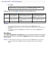

42
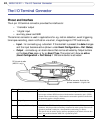
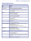
AXIS 210/211 - The I/O Terminal Connector
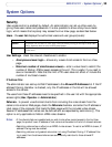
The I/O Terminal Connector
Pinout and Interface
The 4-pin I/O terminal connector provides the interface to:
• 1 transistor output
• 1 digital input
• auxiliary power and GND
The terminal connector is used in applications for e.g. motion detection, event triggering,
time lapse recording, alarm notification via email, image storage to FTP locations, etc.
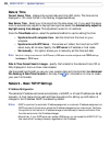
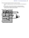
• Input - for connecting e.g. a doorbell. If the doorbell is pressed, the state changes
and the input becomes active (shown under Event Configuration > Port Status).
• Output - connects e.g. an alarm device that can be activated by Output buttons
on the Live View page, or by an Event Type. The output will show as active
(Event Configuration > Port Status) if the alarm device is activated.
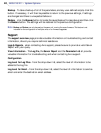
Pin Function Description
4 Transistor Output With a maximum load of 100mA and a maximum voltage of 24V DC, this output
has an open-collector NPN transistor with the emitter connected to pin 1 (GND).
If used with an external relay, a diode must be connected in parallel with the load,
for protection against voltage transients.
3 Digital Input Connect to GND to activate, or leave floating (or unconnected) to deactivate.
2 Auxiliary DC Power Input 7-20 VDC/min 7W. Electrically connected in parallel with the PS-K power
connector, this pin provides an auxiliary connector for mains power to the unit. If
the unit is powered via this pin, a fuse should be used (rating: 1A Slow).
This pin can also be used to power auxiliary equipment, max 100mA, but note that
this is not
possible when the AXIS 211 is powered by PoE.
1GND
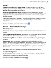
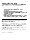
Terminal connector. Note that the
pins are numbered 1-4, right to left.
DC-Iris control cable
(AXIS 211 only).
4321