


AXIS 212 PTZ/ AXIS 212 PTZ-V Installation Guide Page 5
ENGLISH
Installing the hardware
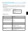
Refer to the illustration on page 4 for a detailed overview of the AXIS 212 PTZ/AXIS 212
PTZ-V. Make a note of the serial number (S/N), which is located on the product label on the
base of the camera unit casing. The serial number is used in the installation. The AXIS 212
PTZ/AXIS 212 PTZ-V is designed for indoor use only.
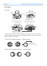
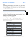
Wall mount
1. To install the camera at an angle from the wall, use
the angled wall mount.
2. For AXIS 212 PTZ, you can cut the plastic to route the
cables to the camera, if necessary.
3. Install the angled wall mount on the wall using the
appropriate screws and plugs.
4. Use the supplied screws (12mm) to attach the camera
unit to the angled wall mount. The camera must be
mounted with the network connector facing upwards.
5. Proceed to Connecting the cables, below.
Notes:
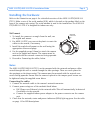
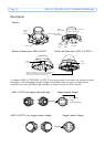
The AXIS 212 PTZ/AXIS 212 PTZ-V can be mounted with the network and power cables
routed through the wall or routed through the side openings. There are cover plates for
the openings on the dome casing. The camera must be mounted with the network con-
nector facing upwards. Ensure that the camera is placed so the tamper-proof screws can
be tightened using the supplied screw driver.
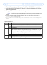
Connecting the cables
1. Connect the network cable to the camera’s network connector.
2. Connect power using one of the methods listed below:
• PoE (Power over Ethernet) via the network cable. This will automatically be detected
if available via the network.
• Connect the supplied indoor power adapter to the power connector on the camera
unit.
3. Check that the network, status and power indicators (LEDs) light up green. See the table
on page 12 for LED descriptions.
Network
connector
up