


Page 6 AXIS 212 PTZ/ AXIS 212 PTZ-V Installation Guide
Completing the installation
1. Use a blower to remove dust from the lens.
2. Clean the dome with a dry soft cloth to remove dust and finger prints (for AXIS 212
PTZ-V only).
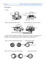
3. Mount the casing using the supplied tamper-proof screws and screw driver.
For AXIS 212 PTZ
If using the angled wall mount, hook the side of the casing onto the tab on the angled
wall mount (see page 4) and secure the dome casing on the other side using a tamper-
proof screw.
For AXIS 212 PTZ-V
If using the angled wall mount, place the dome casing onto the angled wall mount (see
page 4) making sure that the dome casing fits into the slot between the two tabs, and
secure the dome casing on the other side using a tamper-proof screw.
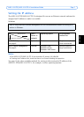
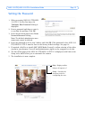
4. Refer to Setting the IP address on page 7 for information on how to assign an IP address
to the AXIS 212 PTZ/AXIS 212 PTZ-V.
The installation is now complete.
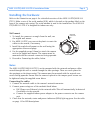
I/O terminal connector block
Pin Function Description
4Transistor
Output
With a maximum load of 50mA and a maximum voltage of 24V DC, this output
has an open-collector NPN transistor with the emitter connected to the GND
pin. If used with an external relay, a diode must be
connected in parallel with the load, for protection against voltage
transients.
3Digital
Input
Connect to GND to activate, or leave floating (or unconnected) to
deactivate.
2 3.3V DC Can be used to power auxiliary equipment, max 50mA.
1GND