


AXIS M1034-W Network Camera
Technical Specifications
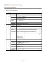
Function Pin Notes
Specications
0 V DC (-)
1
0 V DC
DC output
2
Can be used to power auxiliary equipment.
Note: This pin can only be used as power out.
3.3 V DC
Max load = 50 mA
Digital input
3
Connect to pin 1 to activate, or leave oating (unconnected)
to deactivate
0 to max 40 V DC
Digital output
4
Connected to pin 1 when activated, oating (unconnected)
when deactivated. If used with an inductive load, e.g. a relay,
a diode must be connected in parallel with the load, for
protection against voltage transients.
0 to max 40 V DC, open drain,
100 mA
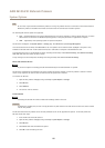
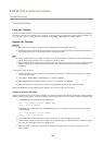
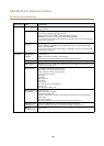
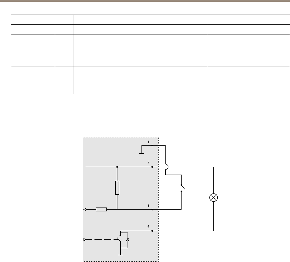
Connection Diagrams
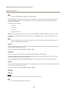
I/O Connector
1
2
3
4
1
0 V DC (-)
2
DC output 3.3 V, max 50 mA
3
Digital input 0 to max 40 V DC
4
Digital output 0 to max 40 V DC, open drain, 100 mA
Performance Considerations
When setting up your system, it is important to consider how various settings and situations will affect performance. Some factors
affect the amount of bandwidth (the bit rate) required, others can affect the frame rate, and some affect both. If the load on the
CPU reaches its maximum, this will also affect the frame rate.
The following factors are among the most important to consider:
• High image resolution and/or lower compression levels result in images containing more data. Bandwidth affected.
• Access by large numbers of Motion JPEG and/or unicast H.264 clients. Bandwidth affected.
• Simultaneous viewing of different streams (resolution, compression) by different clients. Effect on frame rate and
bandwidth.
66