


AXIS M1034-W Network Camera
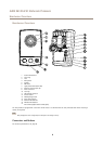
Hardware Overview
Network Connector
RJ45 Ethernet connector.
NONO
NO
TICETICE
TICE
The product shall be connected using a shielded network cable (STP). All cables connecting the product to the network shall
be intended for their specic use. Make sure that the network devices are installed in accordance with the manufacturer’s
instructions. For information about regulatory requirements, see Electromagnetic Compatibility (EMC) on page 2 .
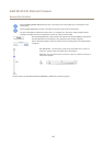
I/O Connector
Use with external devices in combination with, for example, tampering alarms, motion detection, event triggering, time lapse recording
and alarm notications. In addition to the 0 V DC reference point and power (DC output), the I/O connector provides the interface to:
• Digital output – For connecting external devices such as relays and LEDs. Connected devices can be activated by the
VAPIX® Application Programming Interface, output buttons on the Live View page or by an Action Rule. The output will
show as active (shown under System Options > Ports & Devices) if the alarm device is activated.
• Digital input – An alarm input for connecting devices that can toggle between an open and closed circuit, for example:
PIRs, door/window contacts, glass break detectors, etc. When a signal is received the state changes and the input becomes
active (shown under System Options > Ports & Devices).
Power Connector
Mini DC connector. Use the supplied adapter.
Control Button
For location of the control button, see Hardware Overview on page 8 .
The control button is used for:
• Enabling the Focus Assistant. Press and very quickly release the Control button.
• Resetting the product to factory default settings. See page 58.
• Connecting to an AXIS Video Hosting System service. See page 47. To connect, press and hold the button for about 3
seconds until the Status LED ashes green.
• Connecting to AXIS Internet Dynamic DNS Service. See page 47. To connect, press and hold the button for about 3 seconds.
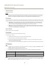
LED Indicators
Note
• The Status LED can be congured to be unlit during normal operation. To congure, go to Setup > System Options > Ports
& Devices > LED. See the online help for more information.
• The Status LED can be congured to ash while an event is active.
• The Status LED can be congured to ash for identifying the unit. Go to Setup > System Options > Maintenance .
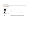
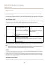
Status LED
Indication
Green Steady green for normal operation.
Amber
Steady during startup and when restoring settings.
Red Flashes red for rmware upgrade failure.
Note
The Network LED can be disabled so that it does not ash when there is network trafc. To congure, go to Setup > System
Options > Ports & Devices > LED. See the online help for more information.
9