


AXIS Q6044-C PTZ Dome Network Camera
Technical Specications
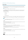
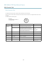
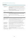
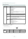
Power connector (DC output)
Two 2-pin terminal blocks for power output (pin 4 is not used).
+ +
21 43
-
Function Pin Notes
Specications
12 V DC
1, 2
Power out to camera Max load = 6.5 A
12.0–13.2 V DC, min 70 W
GND
3
Ground
DC output
N/a
4
N/a
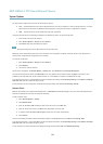
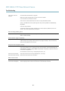
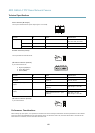
Network connector (internal)
Two 2-pin Ethernet terminal blocks.
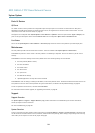
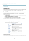
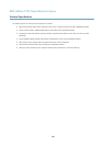
I/O terminal connector (external)
6-pin terminal blocks for:
• Digital Input/Output
• Power (DC output)
• Ground (GND)
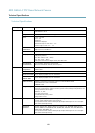
21 43 65
Function Pin Notes
Specications
GND
1, 4, 6
Ground
DC output
2
Power out
12 V DC, 50 mA
Digital input
0 to +30 V DC
Congurable I/O 1 (Input or
Output)
3
Digital output (transistor – open
collector)
Max load = 100 mA
Max voltage = +30 V DC
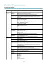
Digital input
0 to +30 V DC
Congurable I/O 2 (Input or
Output)
5
Digital output (transistor – open
collector)
Max load = 100 mA
Max voltage = +30 V DC
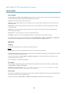
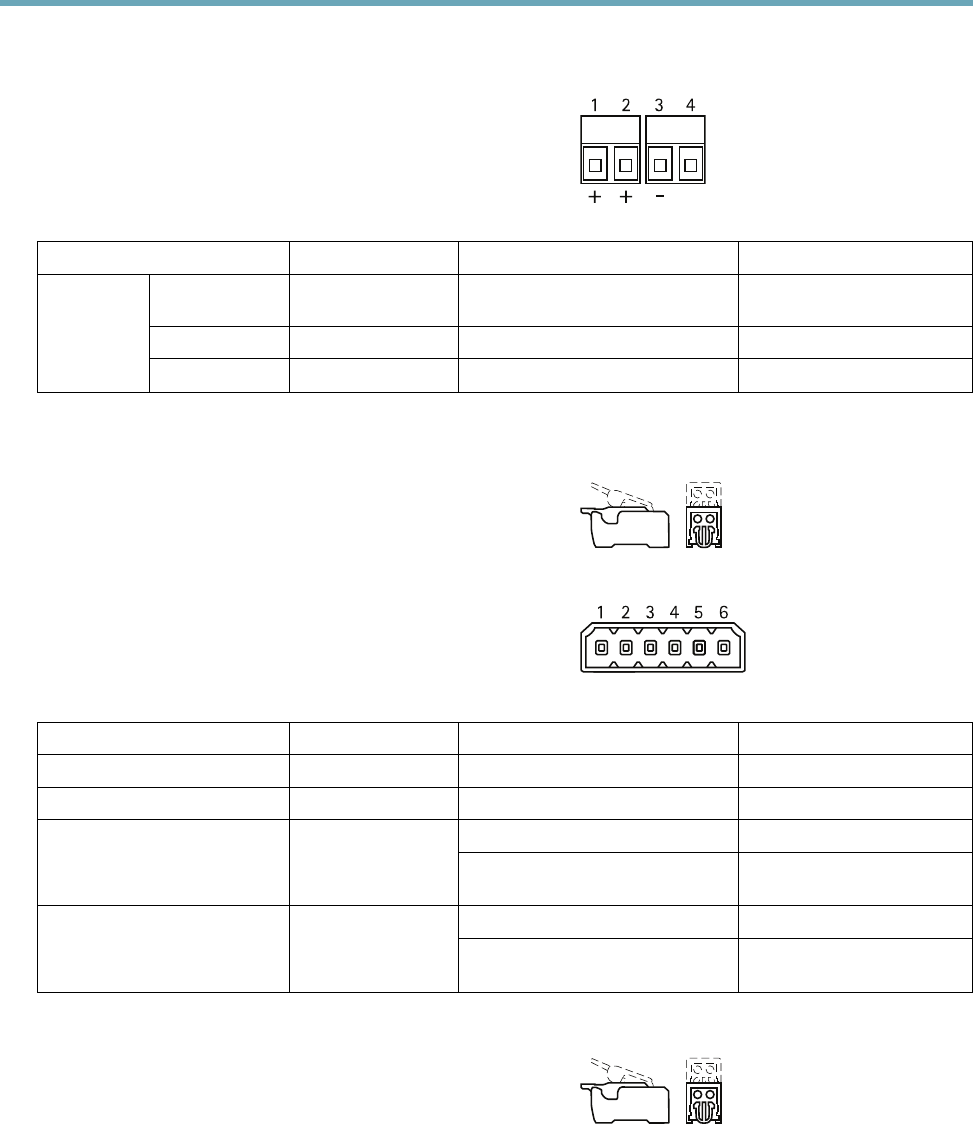
I/O terminal connector (internal)
2-pin terminal block.
Performance Considerations
When settings up your system, it is important to consider how various settings and situations will affect performance. Some factors
affect the amount of bandwidth (the bit rate) required, others can affect the frame rate, and some affect both. If the load on the
CPU reaches its maximum, this will also affect the frame rate.
65