54
Synchronizing the Camcorder’s Time Code
You can synchronize this camcorder’s time code to an external time code generator. You can also
include in the recording the user bit signal received from the TC-IN terminal ( 56). The camcorder
offers the following synchronization options.
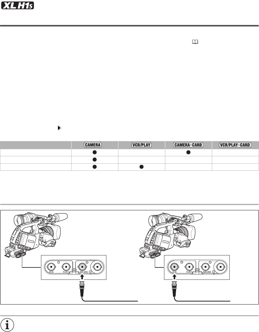
Genlock
When a reference sync signal (analog blackburst or tri-level signal) is input through the GENLOCK terminal,
the V and H phases of the camcorder’s time code will automatically be synchronized to it.
Time Code IN
An external SMPTE-standard LTC timing signal received from the TC-IN terminal will be recorded as the time
code on the tape. The user bit of the external timing signal can also be recorded on tape.
Time Code OUT
The camcorder’s internal time code is sent out from the TC-OUT terminal as a standard LTC timing signal.
When [SIGNAL SETUP] [SDI OUTPUT] is set to [ON(OSD)] or [ON], the time code signal will be output also
through the HD/SD SDI terminal.
* In SD mode, Time Code IN is not available if you select the 24F frame rate (the mode will be canceled and the
“TC·IN” display on the side panel will disappear).
Connection Diagram
* As a reference video signal input you can use either an HD Y signal or an NTSC composite video signal.
While a time code signal is being received, the [FRAME SETTNG] and [COUNT-UP] settings of the
camcorder will be ignored and the external time code’s drop-frame bit will be used instead (if the
external time code is non-drop frame, “NDF” will appear on the side panel).
The Genlock synchronization stabilizes after approx. 10 seconds. After that, the synchronization
will be maintained even if you disconnect the cable from the GENLOCK terminal.
*
Genlock ––
Time Code/User bit IN –––
Time Code OUT ––
Reference video
signal*
SMPTE-standard
LTC timing signal
Genlock Time Code IN


