


CHAPTER 5 PICK-UP/FEEDING SYSTEM
COPYRIGHT
©
1999 CANON INC. CANON PC800s/900s REV.0 AUG. 1999 PRINTED IN JAPAN (IMPRIME AU JAPON)
5-3
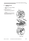
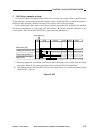
B. Controlling the Pickup Roller
1. Outline
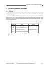
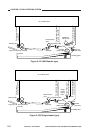
The machine has three types of pickup rollers, i.e., cassette pickup roller, multifeeder pickup
roller, and single-feeder pickup roller, and each of these rollers are operated by the drive of the
main motor switched by means of a gear unit. (In other words, only one roller is driven at any one
time.)
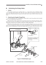
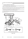
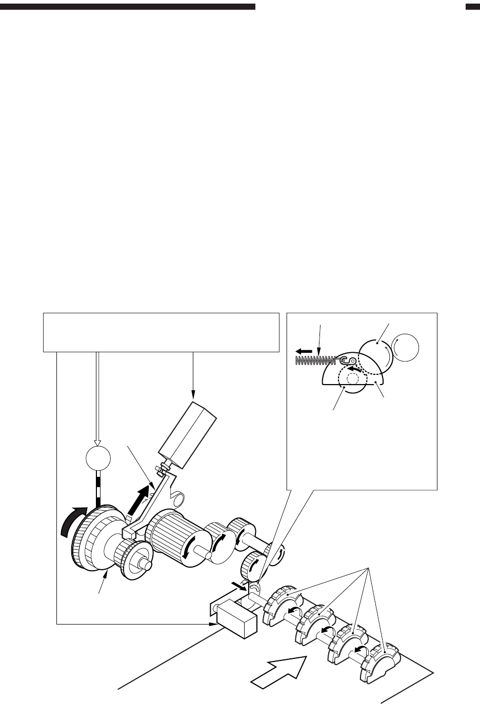
2. Controlling the Cassette Pickup Roller
The cassette pickup roller is controlled by a spring clutch, control ring, pickup clutch solenoid
(SL1), and cassette pickup solenoid (SL5).
When the pickup clutch solenoid turns on, the claw moves away from the control ring, allow-
ing the drive to move to the pickup gear assembly through the spring clutch. Then, when the cas-
sette pickup solenoid turns on, the drive reaches the cassette pickup roller.
When the cassette pickup roller starts to rotate, copy paper is picked up from the cassette and is
sent as far as the registration roller by way of the vertical path roller. The registration roller controls
paper so that its leading edge will match the leading edge of the image on the photosensitive drum.
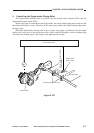
Figure 5-103 (Multifeeder type)
M1
SL5
Copy paper
Cassette pickup rollers
Pickup clutch
SL1
Arm
DC controller PCB
Cassette pickup solenoid drive signal (CPUSD*)
Pickup clutch
solenoid
drive signal
(PUSLD*)
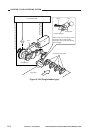
Spring
Pickup roller
Pickup roller gear
Gear
When SL5 turns on, the spring causes
the pickup roller to rotate slightly,
causing the gear and the pickup roller
gear to engage.